| CPC H03F 3/245 (2013.01) [H03F 2200/336 (2013.01); H03F 2200/451 (2013.01)] | 20 Claims |

|
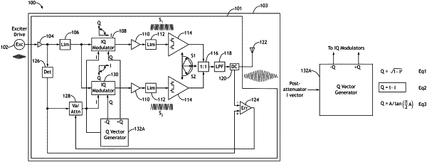
1. A system, comprising:
an input amplifier configured to: receive a radio frequency (RF) drive from an exciter; amplify the RF drive; and output an amplified RF drive, wherein the RF drive includes phase and envelope information of a modulated signal;
an input limiter configured to: receive the amplified RF drive; cap the amplified RF drive to no more than a predetermined voltage; and output a capped amplified RF drive;
a first in-phase component signal (I) and quadrature component signal (Q) modulator (IQ modulator) configured to: receive the capped amplified RF drive; receive an I and a Q; based at least on the I and the Q, produce a zero degree to ninety degree variable phase shifted output signal that changes relative to an input envelope of an RF drive waveform of the RF drive; and output the zero degree to ninety degree variable phase shifted output signal;
a first amplifier path configured to: receive the zero degree to ninety degree variable phase shifted output signal; and output a first phase modulated signal;
a second IQ modulator configured to: receive the capped amplified RF drive; receive the I and a negative Q (−Q); based at least on the I and the −Q, produce a zero degree to negative ninety degree variable phase shifted output signal that changes relative to the input envelope of the RF drive waveform of the RF drive; and output the zero degree to negative ninety degree variable phase shifted output signal;
a second amplifier path configured to: receive the zero degree to negative ninety degree variable phase shifted output signal; and output a second phase modulated signal, wherein the second phase modulated signal is complementary to the first phase modulated signal; and
a vector generator configured to: generate at least the Q and the −Q; output the Q to the first IQ modulator; and output the −Q to the second IQ modulator.
|