| CPC H02M 7/493 (2013.01) [H02J 3/381 (2013.01); H02J 3/40 (2013.01); H02J 3/42 (2013.01); H02J 3/44 (2013.01); H02J 3/46 (2013.01); H02M 1/36 (2013.01)] | 18 Claims |

|
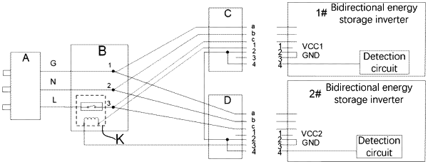
1. A parallel operation connecting device, comprising a control switch, a concentrator, a first connector and a second connector;
wherein the concentrator is connected between an alternating current power supply and the first connector and the second connector to form two identical alternating current lines, and on-off of both of the two alternating current lines is controlled by the control switch;
the first connector is configured to be adaptively connected with a first energy storage inverter, the second connector is configured to be adaptively connected with a second energy storage inverter;
the control switch is configured to turn on to simultaneously switch on the two alternating current lines, when the first connector is connected to the first energy storage inverter and the second connector is connected to the second energy storage inverter;
the control switch is further configured to turn off to simultaneously switch off the two alternating current lines, when the first connector is disconnected from the first energy storage inverter and/or when the second connector is disconnected from the second energy storage inverter;
wherein each of the first connector and the second connector has a signal wire, and the signal wires of the first connector and the second connector are respectively connected with both ends of a control component of the control switch;
when the first connector is connected to the first energy storage inverter and the second connector is connected to the second energy storage inverter, both ends of the control component of the control switch form a control loop through the signal wire of the first connector, an internal line of the first energy storage inverter, an internal line of the second energy storage inverter and the signal wire of the second connector to control the control switch to be turned on.
|