| CPC H02M 7/4826 (2013.01) [H02M 1/0058 (2021.05); H02M 1/126 (2013.01); H02M 5/458 (2013.01); H02M 7/5387 (2013.01)] | 37 Claims |

|
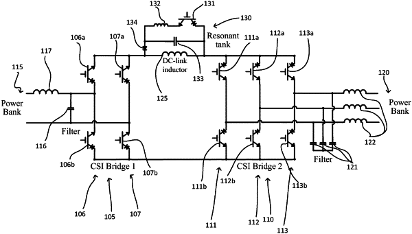
15. A current source inverter (CSI) comprising:
a first CSI bridge operatively connected to a first power bank;
a second CSI bridge operatively connected to a second power bank;
a first DC-link inductor connected in series between the first and second CSI bridges;
a first resonant tank connected in parallel with the first CSI bridge;
a first leakage management diode connected in series with the first resonant tank;
a second resonant tank connected in parallel with the second CSI bridge; and
a second leakage management diode connected in series with the second resonant tank;
wherein the CSI is configured to operate in a switching cycle;
wherein the switching cycle comprises an active phase and a freewheeling phase;
wherein during at least a portion of the active phase, power is transferred simultaneously between:
the first power bank and the first DC-link inductor via the first CSI bridge; and
the second power bank and the first DC-link inductor via the second CSI bridge; and
wherein during the freewheeling phase, no power is transferred between the first DC-link inductor and the first and second power banks.
|