| CPC H02K 1/28 (2013.01) [H02K 1/278 (2013.01)] | 20 Claims |

|
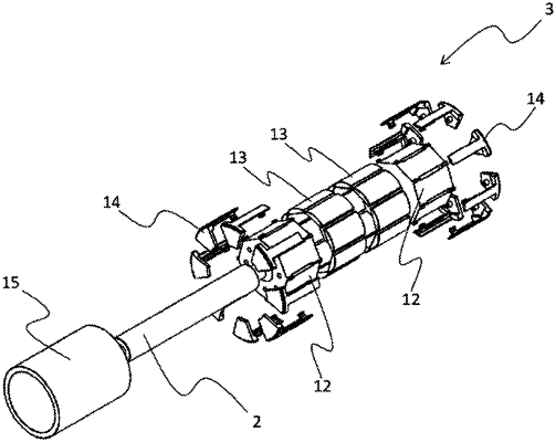
1. A rotor of rotating electric machine, comprising:
a rotor core fixed to an output shaft;
a plurality of magnets arranged on an outer circumference of the rotor core along a circumferential direction of the output shaft; and
a plurality of magnet holders each having an arm portion extending along an axial direction of the output shaft and a base portion retaining the arm portion, wherein
the base portion has a press-fit pin press-fitted into a press-fit hole provided at an end surface of the rotor core,
the arm portion has a holder rib which protrudes inward in a radial direction of the output shaft and of which one end surface in the circumferential direction serves as a pressing surface, and a protrusion inserted into an insertion groove provided at an outer circumferential surface of the rotor core, and
the magnets are located between the rotor core and the magnet holders, one end surface in the circumferential direction of each magnet contacts with the pressing surface, and another end surface in the circumferential direction of each magnet contacts with a core rib protruding from the rotor core.
|