| CPC H02K 1/2781 (2022.01) [H02K 1/2791 (2022.01); H02K 1/28 (2013.01); H02K 3/48 (2013.01)] | 8 Claims |

|
1. A rotor, comprising: a shaft rotating around a rotary axis;
a rotor core comprising a base fixed to the shaft and a plurality of protrusions protruding radially outward from the base and arranged at equal intervals in a circumferential direction; and
a plurality of magnets arranged in the circumferential direction between each two of the plurality of protrusions which are adjacent each other and the base,
wherein two opposite surfaces of each of the plurality of protrusions in the circumferential direction parallel to each other,
wherein an orientation of each of the plurality of magnets is a parallel orientation in which an easy magnetization direction is parallel to a radial direction of a center of the plurality of magnets,
each of the plurality of magnets comprise:
a magnet outer peripheral surface, and a magnet inner peripheral surface in contact with an outer peripheral surface of the rotor core and is arc-shaped viewed from the rotary axis;
two circumferential side faces each of which has a flat surface that contacts one of the two opposite surfaces of the protrusion adjacent to the magnet in the circumferential direction; and
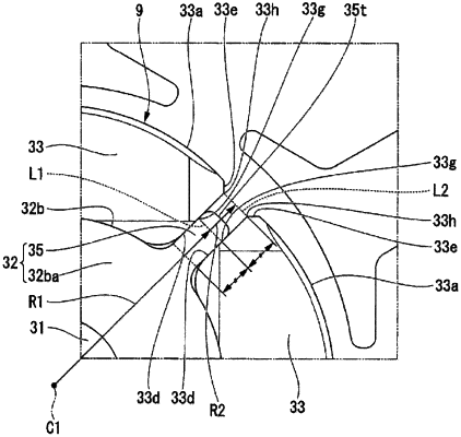
two connection surfaces each of which is connected to one of the two circumferential side faces and to the magnet outer peripheral surface on a radial outer side, and formed so as to gradually approach the center of the magnet in the circumferential direction as directed outward in a protrusion direction of the protrusion, wherein the two connection surfaces are parallel to the easy magnetization direction of the magnet,
wherein the two flat surfaces of the two circumferential side faces of each two magnets which are adjacent in a circumferential direction are parallel to each other,
the rotor core having the base and the plurality of the protrusions are configured to extend over an entirety of the rotor core from one end to the other end of the rotor core in an axial direction;
a position of a front end of each of the plurality of protrusions in the protrusion direction is arranged within an area between a center of each of the two circumferential side faces in the protrusion direction and a crossing ridge portion where the circumferential side face and the connection surface cross.
|