| CPC H02J 7/0031 (2013.01) [B60L 3/0046 (2013.01); H02J 7/007 (2013.01); B60L 3/0092 (2013.01); B60L 2260/26 (2013.01); B60L 2270/20 (2013.01)] | 20 Claims |

|
1. A battery management circuit for use in an electric vehicle and comprising:
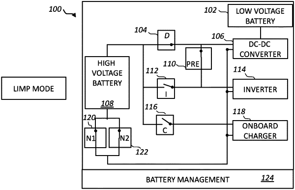
a first output configured to provide a first control signal to a control input of a first contactor having a first terminal coupled to a high voltage battery supply node and a second terminal coupled to a first terminal of a direct current to direct current, DCDC, converter, wherein a second terminal of the DCDC converter is coupled to a low voltage battery supply node;
a second output configured to provide a second control signal to a control input of a second contactor having a first terminal coupled to the high voltage battery supply node and a second terminal coupled to a first terminal of an inverter for an electric motor, wherein the inverter includes a capacitor; and
a third output configured to provide a third control signal to a control input of a third contactor, wherein the third contactor has a first terminal coupled to the second terminal of the first contactor and to the first terminal of the DCDC converter, and has a second terminal coupled to the second terminal of the second contactor and to the first terminal of the inverter;
wherein the battery management circuit is configured to:
during a pre-charge mode, provide a pre-charge current path from the low voltage battery supply node, through the DCDC converter and the third contactor, to the inverter to pre-charge the capacitor in the inverter;
during a drive mode, provide a primary current path from the high voltage battery supply node, through the second contactor, to the inverter to power the electric motor; and
during the drive mode, in response to detecting a fault associated with the second contactor in which the primary current path becomes unavailable, enter a limp mode to provide a secondary current path from the high voltage battery supply node, through the third contactor, to the inverter to power the electric motor.
|