| CPC H01M 50/538 (2021.01) [H01M 4/0402 (2013.01); H01M 4/0471 (2013.01); H01M 10/0422 (2013.01); H01M 10/0431 (2013.01); H01M 50/534 (2021.01); H01M 50/536 (2021.01); H01M 2004/028 (2013.01)] | 14 Claims |

|
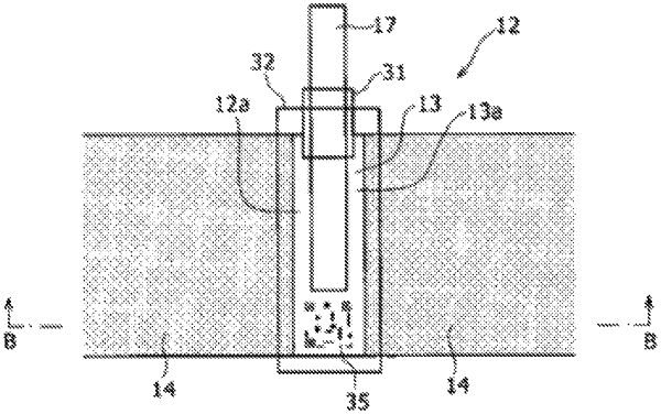
1. A method of manufacturing an electrode plate,
the method comprising:
providing a band-like electrode current collector;
forming an active material layer on each of opposite surfaces of the electrode current collector with an exposed part in which the electrode current collector is exposed;
connecting a current collector lead to the exposed part; and
forming, after formation of the active material layer and the exposed part of the electrode current collector, an identification mark part that enables identification of a manufacturing process history record at a position in the exposed part, the position being different from that of the current collector lead,
wherein:
the exposed part has a rectangular shape and is disposed in a part in a longitudinal direction of the electrode current collector;
on the electrode current collector, the active material layer is disposed at a position on an opposite side in a thickness direction of the electrode current collector from the identification mark part;
the current collector lead and the identification mark part are disposed so as to be aligned in a longitudinal direction of the exposed part;
after the formation of the active material layer and the exposed part of the electrode current collector, the electrode current collector is conveyed on a roller disposed opposite a marker configured to form the identification mark part on the exposed part; and
during formation of the identification mark part, the exposed part has a first side thereof directly facing the marker and a second side opposite the first side thereof supported by the roller via the electrode active material layer interposed between the exposed part and the roller, wherein the electrode current collector, while supported on the roller, forms a curved configuration along the roller, wherein in the curved configuration the exposed part protrudes toward the marker during formation of the identification mark part,
the method further comprising:
attaching a pair of tapes to opposite sides of the electrode current collector, wherein the pair of tapes is configured to sandwich therebetween the current collector lead, the identification mark part, the exposed part, and an edge of the active material layer adjacent to the exposed part together in the thickness direction of the electrode current collector.
|