| CPC H01M 50/14 (2021.01) [H01M 50/15 (2021.01); H01M 50/528 (2021.01); H01M 50/548 (2021.01); H01M 50/627 (2021.01); H01M 50/103 (2021.01); Y02E 60/10 (2013.01)] | 14 Claims |

|
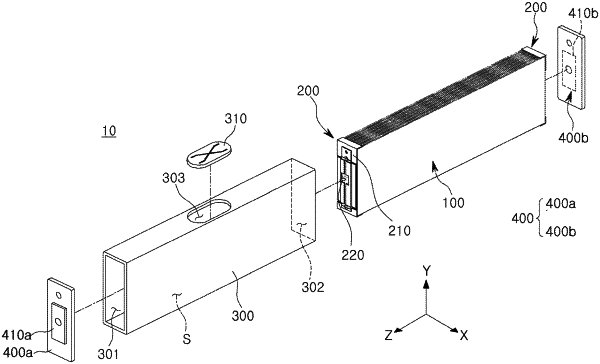
1. A battery cell, comprising:
an electrode assembly in which a plurality of electrode plates are stacked, and the electrode assembly includes a coated portion coated with an active material and uncoated portion not coated with an active material;
a protective assembly disposed on at least one side of the electrode assembly and including an insulating material;
a case having an internal space in which the electrode assembly is accommodated, and
a cap assembly coupled to the case to close the internal space and facing the electrode assembly,
wherein the protective assembly includes:
a current collecting member disposed between the cap assembly and the electrode assembly and electrically connected with the electrode assembly, and includes a first surface facing the cap assembly; and
a protective frame disposed between the current collecting member and the electrode assembly, and supports the current collecting member,
wherein at least a portion of the uncoated portion protrudes toward the cap assembly and is bent to form a bonding portion,
wherein the bonding portion is disposed between the cap assembly and the current collecting member, and configured to contact in the first surface of the current collecting member.
|