| CPC H01J 37/3455 (2013.01) [H01J 37/3405 (2013.01); H01J 37/342 (2013.01); H01J 37/3452 (2013.01); H01J 37/3461 (2013.01); C23C 14/35 (2013.01)] | 18 Claims |

|
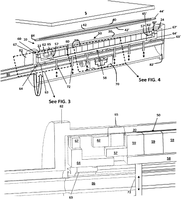
1. An apparatus for sputtering target material onto a substrate based on a plasma confining racetrack having two parallel straight portions and two turnaround portions connecting the two parallel straight portions at ends thereof, said apparatus comprising:
a tubular target having two oppositely opposed ends and a longitudinal axis, the ends respectively being in proximity to the two turnaround portions of said racetrack, said tubular target being rotatable around said longitudinal axis during sputtering operation;
an elongated magnet array supported within said tubular target parallel to the longitudinal axis of said tubular target and configured to generate a plasma-confining magnetic field, said elongated magnet array comprising:
a central stationary portion having two ends oppositely opposed and comprising a plurality of central stationary magnets positioned between the two ends thereof, each of the plurality of central stationary magnets having a first thickness, the central stationary portion additionally having a stationary magnet segment extending respectively from each of the two ends of the central stationary portion, each of the stationary magnet segments having a second thickness that is smaller than the first thickness of the central stationary magnets; and
two axially movable shunts each positioned at the two ends of the central stationary portion and configured to slidably move relative to the two ends of the central stationary portion, each of the shunts having a carried magnet segment positioned thereon, wherein as each of the shunts is slidably moved away from each respective end of the central stationary portion, a dynamic gap is formed between each respective end of the central stationary portion and each respective carried magnet segment, and as each of the shunts is slidably moved toward each respective end of the central stationary portion, each carried magnet segment is configured to nest with each stationary magnet segment, respectively; and
a drive mechanism configured to axially move the shunts of the elongated magnet array parallel to the longitudinal axis of the tubular target to vary a width of each of the dynamic gaps.
|