| CPC H01F 27/2828 (2013.01) [H01F 27/06 (2013.01); H01F 27/24 (2013.01); H01F 41/069 (2016.01)] | 8 Claims |

|
1. A coil device comprising:
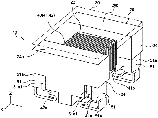
a winding core (i) wound by a wire, (ii) having a winding core axis that is a longitudinal axis of a winding of the wire on the winding core and (iii) having a first end surface at an end of the winding core along the winding core axis;
a flange having (i) an inner end surface connected to the first end surface, (ii) an outer end surface spaced from and opposite to the inner end surface, (iii) a lateral exterior surface connecting the inner end surface and the outer end surface, and (iv) a mounting surface configured to face to a mounting board and arranged perpendicular to the inner end surface, the outer end surface and the lateral exterior surface; and
a terminal fitting attached to the flange, wherein:
the terminal fitting includes:
an engagement part having (i) a first portion in contact with the inner end surface, (ii) a second portion in contact with the outer end surface, and (iii) a third portion in contact with the lateral exterior surface, and
a protrusion plate part connected to the engagement part;
the third portion extends between and connects the first portion and the second portion;
the engagement part and the flange are configured such that the first portion and the second portion apply a clamping force on the inner end surface and the outer end surface to affix the engagement part to the flange;
the protrusion plate part includes (i) a mounting part extending along the mounting surface and configured to be connected to the mounting board and (ii) a connection part extending along the lateral exterior surface between the mounting part and the engagement part; and
the mounting part is connected to a lead end of the wire.
|