| CPC G01V 3/28 (2013.01) [G01V 3/38 (2013.01)] | 5 Claims |

|
1. A logging method based on a time-domain electromagnetic tensor, wherein the logging method comprises:
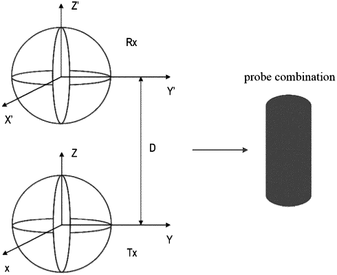
constructing a transmitting coil system Tx and a receiving coil system Rx, wherein the transmitting coil system Tx and the receiving coil system Rx are respectively composed of three coils in different directions and orthogonal to each other, and a borehole probe is formed by the transmitting coil system Tx and the receiving coil system Rx;
setting a measurement point; exciting, through the transmitting coil system Tx, a time-domain electromagnetic field;
receiving, by the receiving coil system Rx located above the transmitting coil system Tx with a distance D, secondary field signals;
receiving the secondary field signals in three component directions simultaneously to obtain nine component data, wherein each component data is a series of induction potentials corresponding to measurement time series one by one;
obtaining, through each measurement time series, a potential sequence or a resistivity value changing over time for a layer where a corresponding measurement point is located; and
obtaining, after a time-depth conversion, a change on a potential or a resistivity of the layer where the corresponding measurement point is located,
wherein a method for obtaining each resistivity value and induction potential of a magnetic field intensity is as follows:
setting a stratigraphic coordinate system (x,y,z) and an instrument coordinate system (x′,y′,z′), setting θ as an azimuth angle of an instrument tilted, and β as a self-rotation angle of the instrument during a measuring process and a rotation angle of the instrument during a descending process, that is the azimuth angle of the instrument;
wherein equivalent magnetic moments in three directions of transmitting coils in the borehole probe are Mx′, My′, Mz′, and a relationship between magnetic field intensities Hx′, Hy′, Hz′, received by receiving coils in three directions of the borehole probe and the equivalent magnetic moments is:
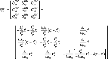
 where G denotes a Dyadic Green's function, R denotes a transformation matrix from the instrument coordinate system to the stratigraphic coordinate system, and RT denotes a transpose matrix of R, and a formula for calculating the Dyadic Green's function G by adopting a transmission line equivalent principle is as follows:
 where GHMmn denotes a Green's function corresponding to a magnetic field generated by a magnetic current source in area n in area m, each matrix element denotes a component in the different directions, GxyHM denotes a component in xy directions, kx, ky and kρ respectively denote propagation coefficients of electromagnetic waves in the three directions, i denotes an imaginary number, ω denotes an angular frequency, μn denotes a magnetic permeability in the area n, μm denotes a magnetic permeability in the area m, z′denotes a field source position, z denotes a field point position, ViP denotes a voltage excited by a unit parallel current source and IiP denotes a current excited by the unit parallel current source, VvP denotes a voltage excited by a unit series voltage source and IvP denotes a current excited by the unit series voltage source, when P is e and h, P denotes a transverse wave and a transverse magnetic wave respectively, and δ denotes a Dirac function; and
calculating magnetic field intensities received by the receiving coils of the borehole probe in a frequency domain, and converting, according to a conversion relationship between a time-domain magnetic field and a frequency-domain magnetic field, the frequency-domain magnetic field into the time-domain magnetic field, and further obtaining the series of induction potentials.
|