| CPC G01R 35/007 (2013.01) [G01R 27/2605 (2013.01)] | 8 Claims |

|
1. A method for testing a sensor within an electronic circuit, the sensor including a first sensor element and a first reference element in a first branch of a Wheatstone bridge circuit, and a second sensor element and a second reference element in a second branch of the Wheatstone bridge circuit, the first branch and the second branch being in parallel with one another, the Wheatstone bridge circuit including a first input for a first reference signal and a second input for a second reference signal, each of the first input and the second input each being connected to the first branch and the second branch, the first reference signal and the second reference signal being provided using a control logic, the control logic being part of the electronic circuit, the first branch includes a first signal output between the first sensor element and the first reference element, and the second branch includes a second signal output between the second sensor element and the second reference element, it being possible to determine a first useful signal at the first signal output and a second useful signal at the second signal output, the first signal output being connected via a first switch to a first amplifier input of an amplifier, the second signal output being connected via a second switch to a second amplifier input of the amplifier, and the amplifier being part of the electronic circuit, the method comprising the following steps:
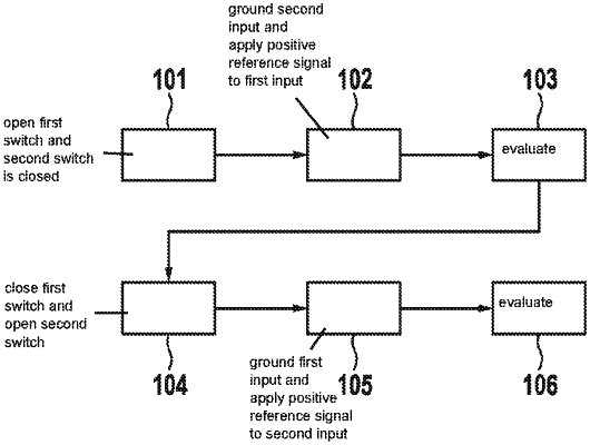
closing the first switch and opening the second switch, and thereafter: (i) applying a positive reference signal to the first input and a negative reference signal to the second input, and (ii) recording the first useful signal;
opening the first switch and closing the second switch, and thereafter: (i) applying a positive reference signal to the first input and a negative reference signal to the second input, and (ii) recording the second useful signal;
evaluating the first useful signal and the second useful signal as to whether damage to the sensor or an electrical connection between the sensor and the electronic circuit exists, wherein a damage to the sensor exists when the first useful signal and the second useful signal have a differing absolute value.
|