| CPC G01N 33/0011 (2013.01) | 7 Claims |

|
1. An in-situ observation device for gas hydrates, comprising:
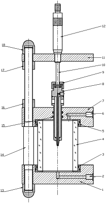
a reactor; wherein the reactor comprises a visual tube, a pulling rod, a temperature-controlled seed crystal rod and a spiral adjuster; an upper end and a lower end of the visual tube are respectively equipped with an upper end cap and a lower end cap, and the upper end cap and the lower end cap are connected to the pulling rod; the upper end cap defines an air inlet, and the lower end cap defines a liquid inlet; an upper end of the temperature-controlled seed crystal rod is connected to an adjusting flange through an adjusting rod; the adjusting flange is connected to the spiral adjuster, and the adjusting flange is connected to the pulling rod; a lower end of the temperature-controlled seed crystal rod hermetically passes through the upper end cap and is located in the visual tube; the temperature-controlled seed crystal rod defines a cooling liquid channel, and a cooling liquid inlet and a cooling liquid outlet which are connected to the cooling liquid channel; and the temperature-controlled seed crystal rod defines a seed crystal rod liquid inlet and a seed crystal rod outlet;
wherein the in-situ observation device for gas hydrates further comprises: a transparent water bath, a first circulating water bath, a gas injection pump, a liquid injection pump, a vacuum pump, a gas cylinder, a camera, a computer, and a second circulating water bath; the reactor is disposed in the transparent water bath; the first circulating water bath is connected to the transparent water bath individually through a first circulation water pipe and a second circulation water pipe; the vacuum pump is connected to the air inlet through a first pipeline, and the gas cylinder is connected to the air inlet through a second pipeline; the gas injection pump is located on the second pipeline, and the liquid injection pump is connected to the liquid inlet through a third pipeline; the second circulating water bath is connected to the cooling liquid inlet and the cooling liquid outlet through a third circulation water pipe and a fourth circulation water pipe; and the camera is located on a side of the transparent water bath, and a signal output terminal of the camera is connected to a signal input terminal of the computer;
wherein the in-situ observation device for gas hydrates further comprises: a pressure sensor located on the second pipeline, and a signal output terminal of the pressure sensor is connected to the signal input terminal of the computer; and
wherein the in-situ observation device for gas hydrates further comprises: a temperature sensor; a sensing terminal of the temperature sensor is located in the transparent water bath, and a signal output terminal of the temperature sensor is connected to the signal input terminal of the computer.
|