| CPC F28F 9/0253 (2013.01) [F16L 37/40 (2013.01); F16L 37/56 (2013.01); G06F 1/20 (2013.01); H05K 7/20272 (2013.01)] | 7 Claims |

|
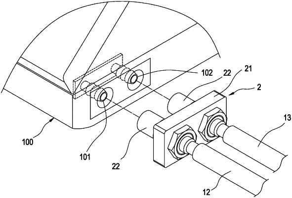
1. A tube connector structure for an electronic device (100), the electronic device (100) comprising a water inlet (101) and a water outlet (102), the tube connector structure (2) comprising:
a connecting plate (21); and
two tube connector plugs (22), passing through and fixed to the connecting plate (21), one of the tube connector plugs (22) connected with the water inlet (101), and another one of the tube connector plugs (22) connected with the water outlet (102);
wherein each tube connector plug (22) comprises a main tube (221), a water blocking member (222) and a first return spring (223), the main tube (221) passes through and is fixed to the connecting plate (21), an inner annular block (2211) is extended on an inner wall of the main tube (221), the water blocking member (222) movably passes the main tube (221), the first return spring (223) is clamped between the main tube (221) and the water blocking member (222) and configured to push the water blocking member (222) to abut against the inner annular block (2211), and the water inlet (101) or the water outlet (102) is configured to push the water blocking member (222) to move away from the inner annular block (2211) when being inserted into the main tube (221);
wherein each water blocking member (222) comprises a block body (2221) and an O-ring (2223), the block body (2221) movably passes the main tube (221), an outer annular block (2222) is extended on an outer wall of the block body (2221), the O-ring (2223) is disposed around the block body (2221) and clamped between the inner annular block (2211) and the outer annular block (2222), and a slant annular groove (2212) is disposed on an end of the inner annular block (2211) adjacent to the O-ring (2223), a depth of the slant annular groove (2212) is gradually decreased toward a direction away from the O-ring (2223).
|