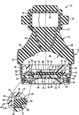
| CPC F16F 13/18 (2013.01) [F16F 13/106 (2013.01)] | 8 Claims |

|
1. A fluid-filled vibration damping device comprising:
a pressure receiving chamber;
an equilibrium chamber;
a partition partitioning the pressure receiving chamber and the equilibrium chamber; and
a movable film within a housing space in the partition, an outer peripheral end of the movable film including
a contact part in contact with a pressure receiving chamber-side wall inner surface of the housing space partially in a circumferential direction, and
a sealing part in contact with an equilibrium chamber-side wall inner surface of the housing space over an entire circumference, wherein
the outer peripheral end of the movable film is supported by the partition,
a gap is between an outer circumferential surface of the movable film and an inner circumferential surface of the housing space that are opposed to each other,
in the outer peripheral end of the movable film, communication passages communicating with the gap are at a position away from the contact part in contact with the pressure receiving chamber-side wall inner surface of the housing space, and
the contact part is constituted by a plurality of elastic protrusions arranged in the circumferential direction of the outer peripheral end of the movable film while spaced apart from each other in the circumferential direction, each of the elastic protrusions protruding toward a side of the pressure receiving chamber with a circular cross section while having a tapered shape,
in the outer peripheral end of the movable film, protruding ends of the elastic protrusions are pressed against the pressure receiving chamber-side wall inner surface of the housing space, while the communication passages are constituted by a plurality of empty spaces maintained circumferentially between the elastic protrusions adjacent to each other in the circumferential direction,
when, based on a relative internal pressure differential arising between the pressure receiving chamber and the equilibrium chamber, a force toward the pressure receiving chamber side acts on the movable film, the outer peripheral end of the movable film is configured to be displaced toward the pressure receiving chamber side due to compressed deformation of the elastic protrusions so that the sealing part is separated from the equilibrium chamber-side wall inner surface of the housing space such that a relief passage through which the pressure receiving chamber and the equilibrium chamber are held in communication is formed including the gap and the communication passage, and
the gap between the outer circumferential surface of the movable film and the inner circumferential surface of the housing space is an annular gap extending entirely in the circumferential direction.
|