| CPC F15B 11/17 (2013.01) [F15B 21/14 (2013.01); F15B 2211/20515 (2013.01); F15B 2211/20561 (2013.01); F15B 2211/20569 (2013.01); F15B 2211/212 (2013.01); F15B 2211/27 (2013.01); F15B 2211/30525 (2013.01); F15B 2211/6658 (2013.01); F15B 2211/7053 (2013.01); F15B 2211/761 (2013.01); F15B 2211/88 (2013.01)] | 5 Claims |

|
1. A motion control device for powering a hydraulic actuator, the motion control device comprising:
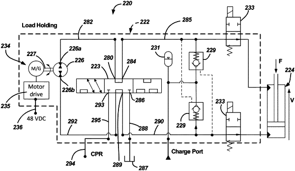
a motion control unit adapted to be hydraulically connected to the hydraulic actuator, the motion control unit also being configured to be electrically connected to an electrical power source and fluidly connected to a hydraulic power source, the motion control unit including an electric motor/generator, a hydraulic pump/motor, and a mode-switching valve configured for allowing blended power from the electrical power source and the hydraulic power source to be transferred to the hydraulic actuator;
wherein the electric motor/generator is mechanically coupled to the hydraulic pump/motor, wherein the hydraulic pump/motor includes a first port and a second port, wherein when the mode-switching valve is in a first position the hydraulic power source fluidly connects to the second port, the first port fluidly connects, via the mode-switching valve, to a first side of the hydraulic actuator, and a second side of the hydraulic actuator fluidly connects, via the mode-switching valve, to a tank; wherein when the mode-switching valve is in a second position different from the first position the hydraulic power source fluidly connects to the second port, the first port fluidly connects, via the mode-switching valve, to the second side of the hydraulic actuator, and the first side of the hydraulic actuator fluidly connects, via the mode-switching valve, to the tank; and when the mode-switching valve is in a third position different from the first position and different from the second position the first port fluidly connects, via the mode-switching valve, to the second side of the hydraulic actuator, the second port fluidly connects, via the mode-switching valve, to the first side of the hydraulic actuator, and the hydraulic power source and the tank are isolated from the hydraulic actuator.
|