| CPC B65D 25/20 (2013.01) [A45F 3/04 (2013.01); A45F 3/14 (2013.01); B25H 3/02 (2013.01); B65D 21/086 (2013.01); A45F 2003/144 (2013.01); B62B 1/16 (2013.01); B62B 1/20 (2013.01); B62B 3/005 (2013.01); B62B 3/10 (2013.01); B62B 3/102 (2013.01); B62B 5/0433 (2013.01)] | 15 Claims |

|
1. A storage system comprising:
a first storage container comprising:
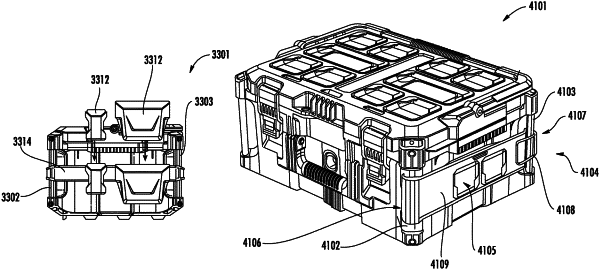
a first cleat receptacle configured at a first top face of the first storage container, the first cleat receptacle comprising two sidewalls, a back wall, and a wing, the back wall extending between the two sidewalls, the two sidewalls and the back wall projecting from a first coupling surface of the first top face, and the wing extending away from the back wall in a first direction above the first coupling surface;
a first lid pivotally attached to the first storage container; and
a first toggle locking latch configured to latch the first lid in a closed position; and
a second storage container comprising:
a first projection extending from a bottom surface of the second storage container, the first projection comprising a projection portion extending in a second direction opposite the first direction, the projection portion of the second storage container is engageable with the wing such that the projection portion engages between the wing and the first coupling surface, wherein attaching engagement between the second storage container and the first storage container takes place when the projection portion and the wing are engaged, thereby restricting separation between the second storage container and the first storage container;
a second lid pivotally attached to the second storage container;
a second toggle locking latch configured to latch the second lid in a closed position;
a front face;
a rear face opposite the front face;
a first side face;
a second side face opposite the first side face;
a first mounting rail coupled to the second storage container and extending between the front face and the first side face, the first mounting rail defining a first outer surface that faces away from each of the front face and the first side face, wherein the first mounting rail is formed from a first material comprising metal; and
a second mounting rail coupled to the second storage container and extending between the rear face and the first side face, and the second mounting rail defining a second outer surface that faces away from each of the rear face and the first side face, wherein the second mounting rail is formed from the first material;
a locking aperture defined by the first storage container; and
a latch member coupled to the second storage container, the locking aperture configured to receive the latch member, wherein disconnecting the second storage container from the first storage container can be performed only after disengaging the latch member from the locking aperture.
|