| CPC B60Q 1/05 (2013.01) [B60Q 1/0058 (2013.01); B60Q 1/2692 (2013.01); F21S 41/24 (2018.01); F21S 41/635 (2018.01); B60Q 2400/30 (2013.01)] | 9 Claims |
|
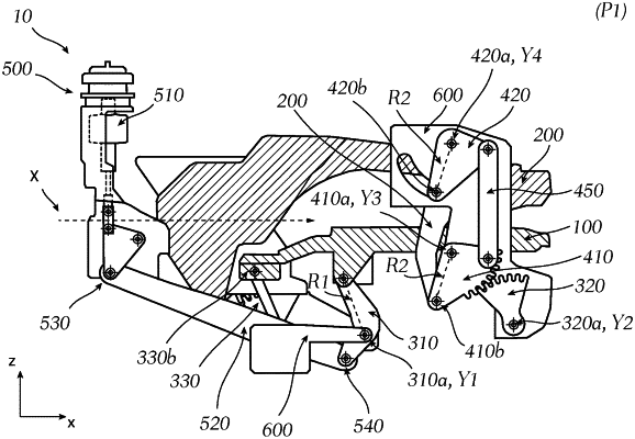
1. An illumination device (10) for a motor vehicle headlamp, the illumination device (10) comprising:
at least one light module (20) configured to illuminate light along a light path in a main direction (X);
a movable lower light guide element (100) and a movable upper light guide element (200);
a motion device for a movement of the lower and upper light guide element (100, 200) with respect to each other between
a closed position (P1), wherein the lower and upper light guide element (100, 200) are—as seen in the main direction (X)—in front of the at least one light module (20) at least partially blocking the light path of the at least one light module (20), wherein the lower and upper light guide element (100, 200) are configured to emit light in the main direction (X), when in the closed position (P1), and
an opened position (P2), wherein the lower and upper light guide element (100, 200) are moved away from the light path of the at least one light module to unblock the light path of the at least one light module (20),
while maintaining their spatial orientation; and
a frame (600), which is stationary in relation to the movement of the lower and upper light guide element (100, 200), wherein the motion mechanism is mounted on the frame (600),
wherein the motion device comprises:
a lower motion mechanism for a movement of the lower light guide element (100) between the closed and opened position (P1, P2), said lower motion mechanism comprises:
a first lower motion element (310) with at least two bearing points, wherein the first lower motion element (310) is pivotably connected to the frame (600) via a fixed bearing point (310a) and pivotably connected to the lower light guide element (100) via a floating bearing point (310b), wherein the floating bearing point (310b) has a distance to the fixed bearing point (310a) on the first lower motion element (310) and is movable along a circular path around a first rotation axis (Y1) determined by the fixed bearing point (310a) with a determined radius (R1) given by the distance between the floating bearing point (310b) to the fixed bearing point (310a), and
a second lower motion element (320) with at least two bearing points, wherein the second lower motion element (320) is pivotably connected to the frame (600) via a fixed bearing point (320a) and pivotably connected to the lower light guide element (100) via a floating bearing point (320b), wherein the floating bearing point (320b) has a distance to the fixed bearing point (320a) on the second lower motion element (320) and is movable along a circular path around a second rotation axis (Y2) determined by the fixed bearing point (320a) with a determined radius (R1) given by the distance between the floating bearing point (320b) to the fixed bearing point (320a),
wherein the first and second rotation axis (Y1, Y2) are orthogonal to the main direction (X) and are parallel to each other, wherein distance of the floating bearing point (310b, 320b) and the fixed bearing point (310a, 320a) of the first and second lower motion element (310, 320) is the same, and wherein the circular paths of the first and second lower motion elements (310, 320) are spatially separated, but are identical, so that the first and second lower motion element (310, 320) have the same deflection, and wherein the floating bearing points (310b, 320b) of the first and second lower motion element (310, 320) are arranged and movable above the respective fixed bearing points (310a, 320a) viewed in an installed state of the illumination device (10) in a motor vehicle,
wherein the first lower motion element (310) is mechanically engaged with a drive device (500) configured to move the first lower motion element (310), and wherein the first and second lower motion elements (310, 320) are connected via the lower light guide element (100) in a way, so that the first and second lower motion elements (310, 320) are movable by the same deflection about their respective fixed bearing point (310a, 320a) when the first lower motion element (310) is moved by the drive device (500), and
wherein the first and second lower motion element (310, 320) are movable between a first deflection and a second deflection, causing the movement of the lower light guide element (100) between the closed and opened position (P1, P2), while the lower light guide element (100) maintaining its spatial orientation due to the same radius (R1) and deflection of the first and second lower motion elements (310, 320), wherein the lower light guide element (100) is in the closed position (P1), when the first and second lower motion elements (310, 320) are aligned in the first deflection, and wherein the lower light guide element (100) is in the opened position (P2), when the first and second lower motion element (310, 320) are aligned in the second deflection,
an upper motion mechanism to movement of the upper light guide element (200) between the closed and opened position (P1, P2), wherein said upper motion mechanism comprises:
a first upper motion element (410) with at least two bearing points, wherein the first upper transition element (410) is pivotably connected to the frame (600) via a fixed bearing point (410a) and pivotably connected to the upper light guide element (200) via a floating bearing point (410b), wherein the floating bearing point (410b) has a distance to the fixed bearing point (410a) on the first upper motion element (410) and is movable along a circular path around a third rotation axis (Y3) determined by the fixed bearing point (410a) with a determined radius (R2) given by the distance between the floating bearing point (410b) to the fixed bearing point (410a), and
a second upper motion element (420) with at least two bearing points, wherein the second upper motion element (420) is pivotably connected to the frame (600) via a fixed bearing point (420a) and pivotably connected to the upper light guide element (200) via a floating bearing point (420b), wherein the floating bearing point (420b) has a distance to the fixed bearing point (420a) on the second upper motion element (420) and is movable along a circular path around a fourth rotation axis (Y4) determined by the fixed bearing point (420a) with a determined radius (R2) given by the distance between the floating bearing point (420b) to the fixed bearing point (420a), and
wherein the third and fourth rotation axis (Y3, Y4) are parallel to each other and to the first and second rotation axis (Y1, Y2), wherein the first and second upper motion element (410, 420) having the same radius (R2), and wherein the circular paths of the first and second upper motion elements (410, 420) are spatially separated, but are congruent, so that the first and second upper motion element (410, 420) have the same deflection, and wherein the floating bearing points (410b, 420b) of the first and second upper motion element (410, 420) are arranged and movable below the respective fixed bearing points (410a, 420a) viewed in an installed state of the illumination device (10) in a motor vehicle,
wherein the first upper motion element (410) is mechanically engaged with the second lower motion element (320) in a first transmission connection in a way, so that a rotational movement of the second lower motion element (320) around its fixed bearing point (320a) is transformed into a rotational movement of the first upper motion element (410) around its fixed bearing point (410a) with an opposite rotational direction, wherein the first and second upper motion element (410, 420) are connected via the upper light guide element (200) in a way, so that the first and second upper motion element (410, 420) are movable by the same deflection about their respective fixed bearing point (410a, 420a) when the first upper motion element (410) is moved by the second lower motion element (320),
wherein the first and second upper motion element (410, 420) are movable between a third deflection and a fourth deflection, causing the motion of the upper light guide element (200) between the closed and opened position (P1, P2), while the upper light guide element (200) maintaining its spatial orientation due to the same radius (R2) and deflection of the first and second upper motion elements (410, 420), wherein the upper light guide element (200) is in the closed position (P1), when the first and second upper motion elements (410, 420) are aligned in the third deflection, and wherein the upper light guide element (200) is in the opened position (P2), when the first and second upper motion element (410, 420) are aligned in the fourth deflection,
wherein the lower motion mechanism comprises a third lower motion element (330) with at least two bearing points, wherein the third lower motion element (330) is pivotably connected to the frame (600) via a fixed bearing point (330a) and pivotably connected to the lower light guide element (100) via a floating bearing point (330b), wherein the floating bearing point (330b) has a distance to the fixed bearing point (330a) on the third lower motion element (330) and is movable along a circular path around a fifth rotation axis (Y5) determined by the fixed bearing point (330a) with a determined radius (R1) given by the distance between the floating bearing point (330b) to the fixed bearing point (330a),
wherein the upper motion mechanism comprises a third upper motion element (430) with at least two bearing points, wherein the third upper motion element (430) is pivotably connected to the frame (600) via a fixed bearing point (430a) and pivotably connected to the upper light guide element (200) via a floating bearing point (430b), wherein the floating bearing point (430b) has a distance to the fixed bearing point (430a) on the third upper motion element (430) and is movable along a circular path around a sixth rotation axis (Y6) determined by the fixed bearing point (430a) with a determined radius (R2) given by the distance between the floating bearing point (430b) to the fixed bearing point (430a),
wherein the third upper motion element (430) is mechanically engaged with the third lower motion element (330) in a second transmission connection in a way, so that a rotational movement of the third lower motion element (330) around its fixed bearing point (330a) is transformed into a rotational movement of the third upper motion element (430) around its fixed bearing point (430a) with an opposite rotational direction, and
wherein the illumination device has—viewed in the main direction (X) and in an installed state of the illumination device (10) in a motor vehicle—two opposite lateral sides, wherein on each lateral side only one transmission connection is disposed.
|