US 12,187,173 B2
Vehicle seat
Shinji Sugiyama, Tochigi (JP)
Assigned to TS TECH CO., LTD., Saitama (JP)
Filed by TS TECH CO., LTD., Asaka (JP)
Filed on Sep. 6, 2023, as Appl. No. 18/461,635.
Application 18/461,635 is a continuation of application No. 17/842,323, filed on Jun. 16, 2022, granted, now 11,780,352.
Application 17/842,323 is a continuation of application No. 16/987,591, filed on Aug. 7, 2020, granted, now 11,390,197, issued on Jul. 19, 2022.
Application 16/987,591 is a continuation of application No. 16/230,026, filed on Dec. 21, 2018, granted, now 10,752,136, issued on Aug. 25, 2020.
Application 16/230,026 is a continuation of application No. 14/917,815, granted, now 10,166,888, issued on Jan. 1, 2019, previously published as PCT/JP2014/074685, filed on Sep. 18, 2014.
Claims priority of application No. 2013-193494 (JP), filed on Sep. 18, 2013; application No. 2013-193495 (JP), filed on Sep. 18, 2013; application No. 2013-193496 (JP), filed on Sep. 18, 2013; and application No. 2013-193499 (JP), filed on Sep. 18, 2013.
Prior Publication US 2023/0406173 A1, Dec. 21, 2023
Int. Cl. B60N 2/42 (2006.01); B60N 2/22 (2006.01); B60N 2/427 (2006.01); B60N 2/64 (2006.01); B60N 2/66 (2006.01); B60N 2/68 (2006.01); B60N 2/02 (2006.01)
CPC B60N 2/4228 (2013.01) [B60N 2/2222 (2013.01); B60N 2/42745 (2013.01); B60N 2/64 (2013.01); B60N 2/667 (2015.04); B60N 2/686 (2013.01); B60N 2002/022 (2013.01); B60N 2/026 (2023.08)] 16 Claims
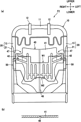
OG exemplary drawing
 
1. A vehicle seat comprising:
a seat frame comprising right and left side frames, and
a plate-shaped pressure-receiving member disposed between the right and left side frames and configured to receive a load from an occupant seated on the vehicle seat, the pressure-receiving member including:
a pressure-receiving portion located in a center of the pressure-receiving member;
right and left support portions extending from upper portions of right and left sides of the pressure-receiving portion, respectively, and
a first reinforcing portion extending diagonally from one of the support portions toward the center of the pressure receiving member; and
the pressure-receiving member having a bend line extending from an upper end to a lower end of the pressure-receiving portion at a laterally center portion of the pressure-receiving portion.