| CPC B29C 45/64 (2013.01) [B29C 2045/645 (2013.01)] | 6 Claims |

|
1. A magnetic clamp device, comprising:
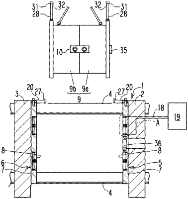
a magnetic plate provided on a side wall of a base;
an adsorption surface formed on a side wall of the magnetic plate, magnetically adsorbing an adsorption object at a predetermined position on the adsorption surface,
a first permanent magnet being inserted into a housing hole formed in the magnetic plate;
a coil wound around an outer periphery of the first permanent magnet;
a magnetic pole member being in contact with the first permanent magnet and being formed from a magnetic material;
a second permanent magnet mounted between an outer peripheral surface of the magnetic pole member and an inner peripheral surface of the housing hole;
a support member protruding from an upper part of the base or the magnetic plate in a direction intersecting the adsorption surface;
a protruding member protruding from the adsorption object, and having an engagement portion configured so as to be received from below by a locking portion provided on the support member, and
wherein the engagement portion is arranged above the locking portion so as to face the locking portion with a predetermined gap therebetween in a state where the adsorption object is adsorbed and fixed at a predetermined position on the adsorption surface, and
wherein a main body portion of the protruding member is screwed to a female threaded hole formed on the upper part of the adsorption object in a vertical direction and a flange portion of the protruding member is protruded in a radial direction of the main body portion from a tip end portion of the main body, thereby the flange portion provides the engagement portion,
wherein the support member has two receiving portions disposed above the adsorption surface and protruding horizontally from the adsorption surface, so as to provide a space sandwiched between the two receiving portions into which the main body portion can be inserted,
wherein the locking portion is formed on an upper surface of each of the two receiving portions.
|