| CPC B29C 45/531 (2013.01) [B29C 45/67 (2013.01)] | 11 Claims |

|
1. An injection device comprising:
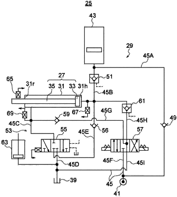
an injection cylinder configured to drive a plunger ejecting a molding material into a mold;
a run-around circuit configured to cause a hydraulic fluid discharged from a rod-side chamber in the injection cylinder along with a forward movement of a piston in the injection cylinder to flow into a head-side chamber in the injection cylinder;
a tank configured to receive the hydraulic fluid discharged from the rod-side chamber along with the forward movement of the piston; and
a servo valve provided in the run-around circuit and connected to the tank, wherein the servo valve comprises one valve element, and is configured to:
achieve a first state where flow from the rod-side chamber to the head-side chamber is permitted while flow from the rod-side chamber to the tank is prohibited by the one valve element moving to a first position, and
achieve a second state where flow from the rod-side chamber to the head-side chamber is prohibited while flow from the rod-side chamber to the tank is permitted by the one valve element moving to a second position, and
control a flow rate of the hydraulic fluid discharged from the rod-side chamber in each of the first state and the second state by adjusting the position of the one valve element.
|