| CPC A61M 39/10 (2013.01) [F16L 37/34 (2013.01); A61M 2039/1027 (2013.01); A61M 2039/1061 (2013.01); A61M 2039/267 (2013.01); F16L 37/46 (2013.01)] | 20 Claims |

|
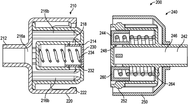
1. A connector comprising:
a first connector portion comprising:
a connector housing comprising:
a connector body defining a tubing opening and a mating opening, wherein the connector body defines a flow path between the tubing opening and the mating opening; and
an engagement portion at least partially surrounding the connector body, the engagement portion defining an engagement lip extending radially toward the connector body, wherein the engagement lip is configured to releasably engage the connector housing with a second connector portion of the connector,
wherein the flow path comprises at least one portion that is normal to the engagement portion, wherein fluid flow through the flow path exerts a normal force on the connector housing and prevent release of the connector housing with the second connector portion of the connector.
|