| CPC A61B 5/205 (2013.01) [A61B 5/07 (2013.01); A61B 5/168 (2013.01); A61B 5/6852 (2013.01); A61B 5/7275 (2013.01); A61L 29/02 (2013.01); A61B 5/150351 (2013.01); A61B 5/154 (2013.01); A61B 5/16 (2013.01); A61B 5/20 (2013.01); A61B 5/202 (2013.01); A61B 5/68 (2013.01); A61B 5/6846 (2013.01); A61B 5/6847 (2013.01); A61B 5/72 (2013.01); A61B 5/7271 (2013.01); A61B 2560/0214 (2013.01); A61B 2562/02 (2013.01); A61B 2562/0247 (2013.01); A61B 2562/164 (2013.01); A61B 2562/166 (2013.01); B01L 3/50825 (2013.01); B01L 2200/06 (2013.01); B01L 2300/04 (2013.01); B01L 2300/044 (2013.01); B01L 2300/046 (2013.01); B01L 2300/14 (2013.01)] | 18 Claims |

|
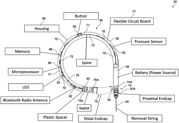
1. A urological monitoring device configured to be inserted into a bladder of a subject, the urological monitoring device comprising:
a tubular housing comprising a first end, a second end opposite the first end, a length extending between the first and second ends, and an interior cavity, the tubular housing comprising a flexible material;
a flexible circuit board positioned within the interior cavity and extending along a portion of the length of the tubular housing;
a processor positioned within the interior cavity and connected to the flexible circuit board;
an antenna positioned within the interior cavity and connected to the flexible circuit board, the antenna configured for wireless communication with an external computing device;
a battery positioned within the interior cavity and connected to the flexible circuit board;
a button positioned within the interior cavity and connected to the flexible circuit board, the button configured to initiate activation of the urological monitoring device;
a pressure sensor positioned within the interior cavity and connected to the flexible circuit board;
a spine positioned within the interior cavity and connected to the flexible circuit board, the spine comprising a first spine end that is positioned adjacent to the battery and a second spine end that is opposite the first spine end, the spine configured to bias the urological monitoring device to an at least partially curved state to facilitate retention of the urological monitoring device within the subject's bladder;
a first endcap connected to the first end of the tubular housing;
a second endcap connected to the second end of the tubular housing;
a spacer positioned within the interior cavity and adjacent to the first endcap, the spacer comprising a body configured to receive the second spine end and inhibit the second spine end from contacting the tubular housing; and
a fluid disposed within the interior cavity and configured to transmit pressure that is applied to the tubular housing from inside the subject's bladder to the pressure sensor.
|