| CPC A61B 17/7079 (2013.01) [A61B 17/7035 (2013.01); A61B 17/7077 (2013.01); A61B 17/708 (2013.01); A61B 17/7083 (2013.01); A61B 2017/681 (2013.01)] | 16 Claims |

|
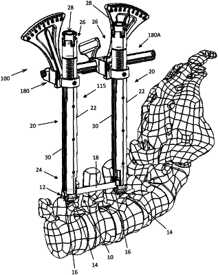
1. A system, comprising:
a spinal fixation construct configured to couple to a first vertebra and a second vertebra in a patient, the spinal fixation construct comprising:
a first pedicle screw including a first shank coupled to a first rod housing,
a second pedicle screw including a second shank coupled to a second rod housing, and
a spinal rod configured to engage the first and second rod housings; and
a first guide assembly configured to couple to the first pedicle screw;
a second guide assembly configured to couple to the second pedicle screw; and
a spinal alignment frame configured to align the first and second vertebra, the spinal alignment frame comprising:
an elongate rack,
a first coupler configured to couple to the elongate rack to the first guide assembly and comprising a first attachment ring configured to receive the first guide assembly therein, a first ring shaft configured to couple to the first attachment ring, wherein the first attachment ring is configured to rotate about a first longitudinal axis of the first ring shaft, and a first indicator arm configured to couple to the first ring shaft, and
a second coupler configured to couple to the elongate rack to the second guide assembly and comprising a second attachment ring configured to receive the second guide assembly therein, a second ring shaft configured to couple to the second attachment ring, wherein the second attachment ring is configured to rotate about a second longitudinal axis of the second ring shaft, and a second indicator arm configured to couple to the second ring shaft;
a first attachment block configured to couple to the first coupler;
a second attachment block configured to couple to the second coupler;
a first housing configured to couple the first attachment block to the elongate rack; and
a second housing configured to couple the second attachment block to the elongate rack.
|