US 12,185,983 B2
Receiver assembly having a vertical tool-engaging slot for independent lock via tooling
Roger P. Jackson, Prairie Village, KS (US); and James L. Surber, Kansas City, KS (US)
Filed by Roger P. Jackson, Prairie Village, KS (US)
Filed on Oct. 9, 2023, as Appl. No. 18/483,252.
Application 18/483,252 is a continuation of application No. 18/055,314, filed on Nov. 14, 2022, granted, now 11,779,374.
Application 18/055,314 is a continuation of application No. 17/467,721, filed on Sep. 7, 2021, granted, now 11,497,532, issued on Nov. 15, 2022.
Application 17/467,721 is a continuation of application No. 16/522,426, filed on Jul. 25, 2019, granted, now 11,109,896, issued on Sep. 7, 2021.
Application 16/522,426 is a continuation of application No. 16/040,258, filed on Jul. 19, 2018, granted, now 10,398,475, issued on Sep. 3, 2021.
Application 16/040,258 is a continuation in part of application No. 15/878,542, filed on Jan. 24, 2018, granted, now 10,172,649, issued on Jan. 8, 2019.
Application 15/878,542 is a continuation in part of application No. 15/338,817, filed on Oct. 31, 2016, granted, now 9,883,892, issued on Feb. 6, 2018.
Application 15/338,817 is a continuation of application No. 13/573,874, filed on Oct. 10, 2012, granted, now 9,480,517, issued on Nov. 1, 2016.
Application 13/573,874 is a continuation in part of application No. 13/573,516, filed on Sep. 19, 2012, granted, now 9,918,745, issued on Mar. 20, 2018.
Application 13/573,874 is a continuation in part of application No. 13/573,303, filed on Sep. 7, 2012, granted, now 9,393,047, issued on Jul. 19, 2016.
Application 13/573,874 is a continuation in part of application No. 13/506,365, filed on Apr. 13, 2012, granted, now 8,444,681, issued on May 21, 2013.
Application 13/573,874 is a continuation in part of application No. 13/374,439, filed on Dec. 29, 2011, granted, now 9,980,753, issued on May 29, 2018.
Application 13/573,874 is a continuation in part of application No. 13/373,289, filed on Nov. 9, 2011, granted, now 9,907,574, issued on Mar. 6, 2018.
Application 13/573,874 is a continuation in part of application No. 12/924,802, filed on Oct. 5, 2010, granted, now 8,556,938, issued on Oct. 15, 2013.
Application 13/573,874 is a continuation in part of application No. 12/802,849, filed on Jun. 15, 2010, abandoned.
Claims priority of provisional application 61/627,374, filed on Oct. 11, 2011.
Claims priority of provisional application 61/626,250, filed on Sep. 23, 2011.
Claims priority of provisional application 61/573,508, filed on Sep. 7, 2011.
Claims priority of provisional application 61/517,088, filed on Apr. 13, 2011.
Claims priority of provisional application 61/463,037, filed on Feb. 11, 2011.
Claims priority of provisional application 61/460,234, filed on Dec. 29, 2010.
Claims priority of provisional application 61/460,267, filed on Dec. 29, 2010.
Claims priority of provisional application 61/456,649, filed on Nov. 10, 2010.
Claims priority of provisional application 61/403,915, filed on Sep. 23, 2010.
Claims priority of provisional application 61/403,696, filed on Sep. 20, 2010.
Claims priority of provisional application 61/402,959, filed on Sep. 8, 2010.
Claims priority of provisional application 61/400,504, filed on Jul. 29, 2010.
Claims priority of provisional application 61/398,807, filed on Jul. 1, 2010.
Claims priority of provisional application 61/396,390, filed on May 26, 2010.
Claims priority of provisional application 61/395,752, filed on May 17, 2010.
Claims priority of provisional application 61/395,564, filed on May 14, 2010.
Claims priority of provisional application 61/343,737, filed on May 3, 2010.
Claims priority of provisional application 61/336,911, filed on Jan. 28, 2010.
Claims priority of provisional application 61/278,240, filed on Oct. 5, 2009.
Claims priority of provisional application 61/270,754, filed on Jul. 13, 2009.
Claims priority of provisional application 61/268,708, filed on Jun. 15, 2009.
Prior Publication US 2024/0032972 A1, Feb. 1, 2024
Int. Cl. A61B 17/70 (2006.01); A61B 17/56 (2006.01); A61B 17/68 (2006.01); A61B 17/86 (2006.01); A61B 90/00 (2016.01)
CPC A61B 17/7037 (2013.01) [A61B 17/7005 (2013.01); A61B 17/7008 (2013.01); A61B 17/702 (2013.01); A61B 17/7038 (2013.01); A61B 17/7082 (2013.01); A61B 17/7091 (2013.01); A61B 17/864 (2013.01); A61B 2017/567 (2013.01); A61B 2017/681 (2013.01); A61B 2090/0808 (2016.02); Y10T 29/49826 (2015.01)] 11 Claims
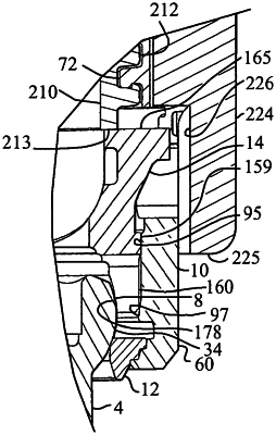
OG exemplary drawing
 
1. A receiver assembly configured for independent locking, via an insert compressing tool, to a head of a bone anchor having an anchor portion implantable into a bone of a patient, prior to securing an elongate rod to the receiver assembly and the bone anchor via a closure top, the receiver assembly comprising:
a receiver comprising a base defining a lower portion of a central bore centered about a vertical centerline axis and communicating with a bottom of the receiver through a lower opening, and a pair of upright arms extending upwardly from the base with opposed interior surfaces defining an open channel configured to receive the elongate rod, the upright arms having top surfaces defining a top of the receiver, opposite front and back surfaces, and outer side surfaces opposite the opposed interior surfaces extending downward from the top surfaces across the base to the bottom of the receiver, the central bore extending upward through the open channel to the top surfaces of the upright arms and including a discontinuous guide and advancement structure proximate the tops of the upright arms and through apertures extending outwardly through at least a portion of each upright arm to the outer side surfaces, the outer side surfaces of each upright arm further comprising:
a vertical tool-engaging slot extending downward from the top surface through to the through aperture and configured to slidably receive the insert compression tool in a direction parallel with the vertical centerline axis of the receiver, and
horizontal tool-engaging grooves located between the top surface of the upright arm and the through aperture and on either side of the vertical tool- engaging slot, each horizontal tool-engaging groove extending laterally to the front surface or the back surface of the upright arm; and
an insert configured for positioning within the central bore of the receiver, the insert having a center opening, a concave lower surface configured to engage the head of the bone anchor, and at least one upward-facing outer engagement surface positionable within one of the through apertures and aligned with one of the vertical tool-engaging slots,
wherein the at least one outer engagement surface of the insert is configured for compressive engagement by a downward-facing surface of the insert compressing tool to independently lock a position of the receiver with respect to the bone anchor.