| CPC A61B 17/295 (2013.01) [A61B 2017/2936 (2013.01); A61B 2017/320094 (2017.08); A61B 2018/00077 (2013.01); A61B 2018/0063 (2013.01); A61B 18/085 (2013.01); A61B 18/1445 (2013.01); A61B 2018/1807 (2013.01); A61B 2018/1861 (2013.01); A61B 34/35 (2016.02); A61B 34/71 (2016.02)] | 20 Claims |

|
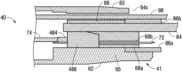
1. An end effector assembly of a surgical instrument, comprising:
a clevis including a proximal body, first and second arms extending distally from the proximal body in spaced-apart relation relative to one another arms, and at least one of: a ceiling extending at least partially between upper portions of the first and second arms, or a floor extending at least partially between lower portion of the first and second arms;
a pivot pin extending transversely at least partially between the first and second arms of the clevis;
a cam pin extending transversely at least partially between the first and second arms of the clevis, the cam pin positioned proximally of the pivot pin;
a first jaw member including a proximal extension portion disposed at least partially within the clevis and a distal jaw body extending distally from the clevis, the proximal extension portion including a first flag disposed between the first and second arms of the clevis and extending vertically at least partially through openings defined within the ceiling and floor to inhibit lateral motion thereof, the first flag defining a pivot aperture through which the pivot pin extends and a cam slot through which the cam pin extends; and
a second jaw member including a proximal extension portion disposed at least partially within the clevis and a distal jaw body extending distally from the clevis, the proximal extension portion including second and third flags disposed between the first and second arms of the clevis in spaced-apart relative to one another and between the ceiling and the floor, the second and third flags fixedly engaged to the clevis, the second and third flags defining pivot apertures through which the pivot pin extends, wherein proximal ends of the second and third flags terminate distally of the cam pin,
wherein the first flag is disposed between the second and third flags in an offset position such that the first flag is disposed closer to the third flag than the second flag, and
a cam block coupled to the cam pin and configured to slide through the clevis to thereby move the cam pin through the cam slot, the cam block having first, second, and third outwardly-facing sides and received within a substantially complementary cavity within the clevis defined by first, second, and third inwardly-facing sides configured to guide the first, second, and third outwardly-facing sides of the cam block, respectively, the first inwardly-facing side defined at least partially by the ceiling of the clevis or the floor of the clevis, the second inwardly-facing side defined at least partially by one of the first or second arms of the clevis, and the third inwardly-facing side defined at least partially by the first flag.
|