| CPC A47L 9/2873 (2013.01) [A47L 5/24 (2013.01); A47L 7/0095 (2013.01); A47L 9/0063 (2013.01); A47L 9/106 (2013.01); A47L 9/1683 (2013.01); A47L 9/22 (2013.01); A47L 9/2815 (2013.01); A47L 9/2842 (2013.01); A47L 9/2884 (2013.01); A47L 9/322 (2013.01); A47L 2201/022 (2013.01); A47L 2201/024 (2013.01)] | 18 Claims |

|
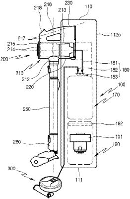
1. A cleaner system comprising:
a cleaner comprising:
a suction part that defines a suction flow path configured to receive air,
a suction motor configured to rotate about a rotation axis to thereby generate suction force for suctioning the air through the suction part,
a cyclone configured to separate dust from the air introduced through the suction part, and
a dust bin configured to store the dust separated by the cyclone; and
a cleaner station that is configured to couple to the cleaner and extends in a longitudinal direction intersecting a longitudinal axis of the dust bin, the cleaner station comprising:
a housing that defines a dust collecting space configured to receive the dust from the dust bin of the cleaner,
a dust collecting motor configured to generate a suction force for suctioning the dust in the dust bin into the dust collecting space, wherein the dust collecting motor and the dust collecting space are arranged along the longitudinal direction of the cleaner station in the housing,
a coupling surface configured to face a bottom surface of the dust bin based on the cleaner being coupled to the cleaner station,
a pair of sidewalls that protrude from the coupling surface in a direction perpendicular to the coupling surface,
a dust bin guide surface disposed between the pair of sidewalls and configured to couple to an outer circumferential surface of the dust bin based on the cleaner being coupled to the cleaner station, wherein the dust bin guide surface and the pair of sidewalls define an accommodating space configured to receive the dust bin based on the cleaner being coupled to the cleaner station, and
a sealer disposed at the dust bin guide surface and configured to be in contact with at least one of the outer circumferential surface or the bottom surface of the dust bin to thereby provide sealing between the dust bin guide surface and a part of the outer circumferential surface of the dust bin based on the cleaner being coupled to the cleaner station,
wherein the sealer is configured to provide the sealing between the dust bin guide surface and the part of the outer circumferential surface of the dust bin based on the dust bin being seated on the sealer after the dust bin is moved in a direction intersecting an imaginary dust bin throughline, the imaginary dust bin throughline extending along the longitudinal axis of the dust bin and passing through the bottom surface of the dust bin.
|