| CPC A45F 3/047 (2013.01) [A45F 3/14 (2013.01); A63B 55/00 (2013.01); A63B 55/408 (2015.10); A45F 2003/146 (2013.01); A63B 2225/09 (2013.01); Y10T 24/3916 (2015.01); Y10T 29/49826 (2015.01)] | 12 Claims |

|
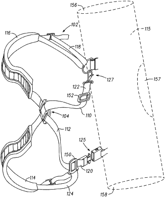
1. A self-adjustable carrying strap system for use with carrying a bag, the system comprising:
a first carrying strap;
a second carrying strap; and
a connector plate comprising a connector plate body having a rear surface and a front surface, the front surface defining a plane;
the connector plate body including a first bridge and a second bridge extending over a footprint of the front surface and offset from the front surface;
the first bridge defining a first channel having a first end and a second end coupled to the front surface, and a straight portion coupled to the first end and the second end, wherein the straight portion of the first bridge is substantially parallel with the front surface;
the second bridge defining a second channel having a first end and a second end coupled to the front surface, and a straight portion coupled to the first end and the second end, wherein the straight portion of the second bridge is substantially parallel with the front surface;
wherein the first channel and the second channel define a first linear pathway along the front surface;
wherein the first bridge and the second bridge are configured to receive the first carrying strap above the front surface;
wherein the first carrying strap while in the first linear pathway is substantially parallel to the front surface without bends or turns in any direction;
wherein a transverse space is defined between the first bridge and the second bridge and forms a second linear pathway in a transverse orientation relative to the first linear pathway;
wherein the second carrying strap while in the second linear pathway is substantially parallel to the front surface without bends or turns in any direction;
wherein the second carrying strap in the second linear pathway passes between the first carrying strap and the front surface of the connector plate;
wherein the first bridge is defined at a first side edge of the connector plate and the second bridge is defined at a second side edge of the connector plate opposite the first side edge;
wherein the first linear pathway and the second linear pathway are defined entirely above the plane defined by the front surface;
wherein the first and second carrying straps overlap each other along the front surface of the connector plate;
wherein the first linear pathway lies along a longitudinal axis;
wherein the second linear pathway lies along a latitudinal axis, and;
wherein the connector plate avoids pinching or clasping the first and second carrying straps allowing them to move without hindrance such that the first carrying strap can move without hindrance approximately along the first linear pathway in a direction of the longitudinal axis, and the second carrying strap can move without hindrance approximately along the second linear pathway in a direction of the latitudinal axis.
|