| CPC A01M 23/24 (2013.01) [A01M 23/245 (2013.01); A01M 23/30 (2013.01)] | 17 Claims |

|
1. An impact kill animal trap comprising:
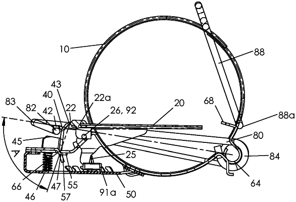
an elongated enclosure with an opening at least at one end thereof and including a top, a bottom, a front, and a rear, the opening being configured to form an entrance for an animal;
a strike bar pivotable at the rear of the enclosure about a pivot axis, the pivot axis being parallel to an elongate axis of the enclosure, a power spring biasing the strike bar to rotate about the pivot axis, the strike bar including two side arms, each of said side arms extending continuously from a proximal end thereof within the enclosure to a distal end thereof beyond the enclosure;
a set mechanism at the front of the enclosure, the set mechanism being configured to selectively hold the strike bar in a bottom set position against a bias from the power spring, the strike bar in the bottom set position extending past the front of the enclosure to the strike bar distal ends of the side arms;
a trip tray pivotably attached to the enclosure at a trip tray pivot at the front of the enclosure, the trip tray including a tray upper position and a tray down position within the enclosure, the trip tray being biased by a tray bias element toward the tray upper position;
a release latch of the set mechanism selectively linked to the trip tray and to a cross bar of the strike bar such that movement of the trip tray from the tray upper position to the tray down position causes the release latch to move and disengage from the strike bar, allowing the strike bar to move from the bottom set position toward the rear of the enclosure, the strike bar moving to an uppermost tripped position under the bias of the power spring; and
a base forming a support structure mounted near the bottom of the enclosure, the support structure extending outward beyond the front of the enclosure, the support structure being vertically aligned with the strike bar distal ends of the side arms in the bottom set position of the strike bar;
wherein the release latch includes a proximal end pivotably attached to the base at a release latch pivot, and in the tray upper position, a tray release edge of the release latch is slidably engaged with a trip tray cam of the trip tray, the release latch is biased by the power spring and separately by a latch biasing element to press the trip tray at the trip tray cam, and the trip tray is separately biased by the tray bias element to hold the trip tray in the tray upper position,
wherein the trip tray is movable between the respective tray upper and tray down positions, and the release latch selectively contacts the trip tray to keep the trip tray in the tray down position.
|