| CPC H05H 1/3405 (2013.01) [H05H 1/34 (2013.01); H05H 1/3421 (2021.05); H05H 1/3478 (2021.05)] | 27 Claims |

|
1. A nozzle for a plasma torch head, laser cutting head or plasma laser cutting head, comprising:
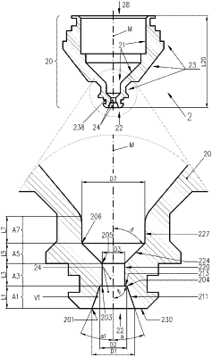
a body with a longitudinal axis M, a front end, a rear end and a nozzle opening at said front end, wherein said nozzle opening at said front end, as viewed from said front end, comprises at least the following portions in a longitudinal sectional view:
a first portion A1 which extends along said longitudinal axis M and which narrows in the direction of said rear end and which has an inner surface and a body edge at said front end,
a second portion A3 which extends along said longitudinal axis M and which has an inner surface and a body edge at the transition from said first portion A1 to said second portion A3; and
at the transition from said first portion A1 to said second portion A3, the diameter D3 of said second portion A3 is between 0.2 mm and 0.6 mm smaller than the diameter D2 and/or the smallest diameter D2 of said first portion A1;
wherein a virtual connecting line V1 between said body edge of said nozzle opening at said front end and said body edge at the transition from said first portion A1 to said second portion A3 and said longitudinal axis M enclose an angle α1 in a range from 15° to 40°, and/or the inner surface of the first portion A1 and the longitudinal axis M enclose an angle α in a range from 10° to 30° and/or the inner surface of said first portion A1 and said longitudinal axis M enclose an angle α1 in a range from 10° to 30°; and
either a virtual connecting line V3 between said body edge at the transition from said first portion A1 to said second portion A3 and said body edge at the transition from said second portion A3 to a third portion A5 and said longitudinal axis M encloses an angle γ1 in a range from 0° to 8°, and widens in the direction of said rear end, or in a range from 172° to 180°, and narrows in the direction of said rear end, or runs parallel to the longitudinal axis M; or
the inner surface of said second portion A3 widens at an angle γ in a range from 0° to 8° in the direction of said rear end or narrows at an angle in a range from 172° to 180° in the direction of said rear end, or runs parallel to the longitudinal axis M.
|