| CPC H02G 3/0412 (2013.01) [H01B 7/04 (2013.01); H01B 7/18 (2013.01); H01B 7/295 (2013.01); H01B 7/421 (2013.01)] | 23 Claims |

|
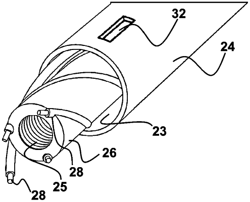
1. A two-stage cable for an electrical power delivery station, the two-stage cable comprising:
a sheath with an axial pathway running a length of the cable between a first end of the cable and a second end of the cable;
a plurality of electrically conductive wires running through the axial pathway of the sheath for the length of the cable, each of the electrically conductive wires configured to communicate electricity from the first end of the cable to the second end of the cable;
one or more fluid conduits immediately adjacent to the plurality of conductive wires within the sheath, each of the fluid conduits having a sidewall surrounding an axial passage thereof that provides a defined flow path for a fluid that is therein to flow between the first end of the cable and the second end of the cable and to cool an interior of the sheath,
wherein each of the electrically conductive wires comprises an insulation coating formed of a material having a first melting temperature, wherein the sidewall of each of the fluid conduits is formed of a material having a second melting temperature that is less than the first melting temperature, and wherein the sidewall of each of the fluid conduits melts and causes an emission of the fluid from the respective flow path and into the interior of the sheath at a location along the length of the cable where a temperature of one or more of the plurality of electrically conductive wires at the location exceeds the second melting temperature.
|
|
11. A cable system for an electrical power delivery station, comprising:
a two-stage cable, comprising:
a sheath with an axial pathway running a length of the cable between a first end of the cable and a second end of the cable;
a plurality of electrically conductive wires running through the axial pathway of the sheath for the length of the cable;
one or more fluid conduits immediately adjacent to the conductive wires within the sheath, each of the fluid conduits having a sidewall surrounding an axial passage thereof that provides a defined flow path for a fluid that is therein to flow between the first end of the cable and the second end of the cable and to cool an interior of the sheath; and
a junction box comprising a fluid chamber comprising an internal cavity configured to hold a supply of the fluid,
wherein the plurality of conductive wires and the one or more fluid conduits are engageable with the junction box such that the axial passage of each of the fluid conduits is fluidly and sealingly coupled to the internal cavity.
|
|
20. A two-stage vehicle cable for an electrical power delivery station, comprising: a sheath with an axial pathway running a length of the cable between a first end of the cable and a second end of the cable; a plurality of electrically conductive wires running through the axial pathway of the sheath for the length of the cable, each of the electrically conductive wires configured to communicate electricity from the first end of the cable to the second end of the cable; one or more first fluid conduits immediately adjacent to the conductive wires within the sheath, each of the first conduits having a first sidewall surrounding a first axial passage thereof that provides a first defined flow path for a fire suppressant therein to flow between the first end of the cable and the second end of the cable; and one or more second fluid conduits immediately adjacent to the conductive wires within the sheath, each of the second conduits having a second sidewall surrounding a second axial passage thereof that provides a second defined flow path for a non-conductive coolant that is therein to flow between the first end of the cable and the second end of the cable and is configured to cool an interior of the sheath, wherein each of the electrically conductive wires comprises an insulation coating formed of a material having a first melting temperature, wherein the sidewall of each of the first and second fluid conduits is formed of a material having a second melting temperature that is less than the first melting temperature, and wherein the sidewall of each of the first and second fluid conduits melts and causes an emission of the fluid from the respective flow path and into the interior of the sheath at a location along the length of the cable where a temperature of one or more of the plurality of electrically conductive wires at the location exceeds the second melting temperature.
|