| CPC G01R 31/31926 (2013.01) [G01R 31/318566 (2013.01); G01R 31/318572 (2013.01)] | 18 Claims |
|
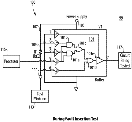
1. A logic gate system for fault insertion testing, comprising:
a logic gate module having:
a plurality of input pins, the plurality of input pins comprising:
an input signal pin configured to receive an input signal;
a power supply input pin configured to receive power from a power supply; and
a test input pin; and
an output pin connected to the input pins via one or more logic gates;
a power supply line connected to the power supply input pin and the test input pin; and
a zero-ohm jumper resistor disposed between the power supply input pin and the test input pin, wherein the zero-ohm resistor is configured to be replaced with a low ohm resistor to allow reverse driving a voltage on the test input pin, wherein the one or more logic gates are configured to reverse an output at the output pin when the voltage on the test input pin is reverse driven.
|