| CPC F16B 5/0088 (2013.01) [F16B 7/0406 (2013.01)] | 17 Claims |

|
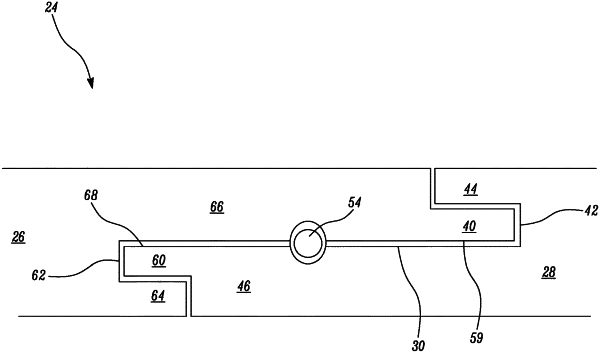
1. A joint assembly joining first and second annular components about a common axis extending along an interface between the first and second annular components,
the first annular component comprising a first end portion having a radially outwardly facing surface shaped to fit radially inside a second surface of a hollow second end portion of the second annular component so as to form an interface between the opposing first and second surfaces,
wherein the first and second surfaces each comprise a concavity extending laterally with respect to the common axis such that when the first and second surfaces are opposingly arranged the opposing concavities define a cavity at the interface,
the assembly comprising a retaining member insertable into the cavity at the interface to prevent axial separation of the first and second components,
wherein one of the first and second end portions comprises a free end axially spaced from the concavity and the other of the first and second end portions comprises an axially extending recess arranged to receive the free end, wherein the free end includes a protrusion that is axially insertable into the recess and the recess thereby covering both opposing side surfaces of the protrusion so as to prevent relative movement between the first and second component in a radial direction, the protrusion having an end face substantially perpendicular to a direction of the extending axis,
wherein the first and second end portions are annular in form and the protrusion and/or recess extends in a circumferential direction, and
wherein the protrusion end face includes a tenon projecting from a portion of the protrusion end face, the portion being less than an entire portion of the protrusion end face, the recess includes a corresponding slot arranged to receive the projecting tenon, and when the projecting tenon is received in the slot, both side surfaces of the projecting tenon are fully covered by the slot.
|