| CPC F04C 29/028 (2013.01) [F04C 18/0215 (2013.01); F04C 29/005 (2013.01); F04C 29/023 (2013.01); F04C 2240/30 (2013.01); F04C 2240/40 (2013.01); F04C 2240/603 (2013.01); F04C 2240/807 (2013.01)] | 10 Claims |

|
1. A scroll compressor, comprising:
a shell, an oil pool for storing lubricating oil being formed at a bottom of the shell;
a scroll assembly disposed in the shell, and the scroll assembly comprising:
a fixed scroll fixed in the shell,
an orbiting scroll disposed below the fixed scroll and cooperating with the fixed scroll to form a compression chamber, and
a housing fixed in the shell and supporting the orbiting scroll below the orbiting scroll, thereby forming a friction pair between a lower surface of the orbiting scroll and an upper surface of the housing; and
a drive assembly, comprising:
an electric motor,
a crankshaft drivable by the electric motor to rotate, an upper end of the crankshaft being cylindrical and inserted into a center hole of a hub at a bottom of the orbiting scroll to drive the orbiting scroll to revolve, and
an upper counterweight disposed at the upper end of the crankshaft and rotating with the crankshaft, the upper counterweight having an upper surface and an upright wall extending upwards from the upper surface of the upper counterweight, the upright wall being a part of a cylindrical body, and the hub of the orbiting scroll being inserted into a gap between an outer peripheral surface of the upper end of the crankshaft and an inner wall surface of the upright wall;
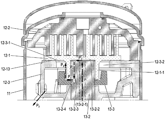
wherein, the scroll compressor further comprises a lubricating oil supply system, and the lubricating oil supply system comprises:
an oil passage P1 formed by a core hole extending longitudinally through the crankshaft;
an oil pump installed at a lower end of the crankshaft, wherein an oil suction port at the lower end of the oil pump is immersed in the lubricating oil in the oil pool, and an oil outlet at an upper end of the oil pump is connected to the oil passage P1;
an oil passage P3 located in a gap between an upper end surface of the crankshaft and the lower surface of the orbiting scroll;
an oil passage P4 formed by a longitudinal hole in the crankshaft, the longitudinal hole extending downwards from the upper end surface of the crankshaft;
an oil passage P5 formed by a transverse hole in the crankshaft and a gap between a lower edge of the hub of the orbiting scroll and the upper surface of the upper counterweight, wherein the transverse hole extending transversely from the outer peripheral surface of the upper end of the crankshaft to communicate with the longitudinal hole, an opening of the transverse hole on the outer peripheral surface of the upper end of the crankshaft is aligned with the gap between the lower edge of the hub of the orbiting scroll and the upper surface of the upper counterweight;
an oil passage P6 formed by a gap between an outer peripheral surface of the hub of the orbiting scroll and the inner wall surface of the upright wall, and a gap between the outer peripheral surface of the hub of the orbiting scroll and an inner peripheral surface of a center hole of the housing; and
an oil passage P2 formed by an oil return pipe, an upper end opening of the oil return pipe being located at a bottom of the housing, and a lower end opening of the oil return pipe leading to the oil pool to circulate the lubricating oil along the following route:
from the oil pool to the oil pump, then to the oil passage P1, then to the oil passage P3, then to the oil passage P4, then to the oil passage P5, then to the oil passage P6, then to the friction pair, then to the oil passage P2, and then returning to the oil pool.
|