| CPC F02K 1/70 (2013.01) [F02K 3/06 (2013.01); F02K 3/075 (2013.01); F05D 2240/14 (2013.01); F05D 2260/606 (2013.01)] | 14 Claims |

|
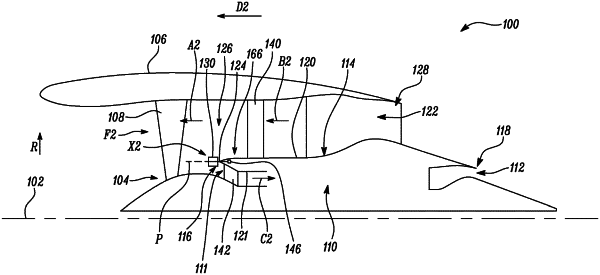
1. A gas turbine engine having a principal rotational axis, the gas turbine engine comprising:
a fan coaxial with the principal rotational axis;
a nacelle circumferentially surrounding the fan;
a core engine disposed downstream of the fan and extending along the principal rotational axis;
a core engine casing circumferentially surrounding the core engine around the principal rotational axis, wherein the core engine casing extends along the principal rotational axis from a first casing end to a second casing end downstream of the first casing end, wherein the first casing end is proximal to the fan, and wherein the core engine casing comprises a casing outer surface and a casing inner surface;
a bypass duct defined between the nacelle and the casing outer surface;
a core engine duct at least partially defined by the casing inner surface;
a plurality of outlet guide vanes arranged around the principal rotational axis and coupled to the core engine casing, wherein each outlet guide vane from the plurality of outlet guide vanes radially extends outwards from the casing outer surface into the bypass duct;
a plurality of stator vanes coupled to the core engine casing proximal to the first casing end, wherein each stator vane from the plurality of stator vanes radially extends inwards from the casing inner surface into the core engine duct; and
a plurality of flaps pivotally coupled to the core engine casing and arranged circumferentially around the principal rotational axis, wherein each flap from the plurality of flaps extends from the first casing end towards the fan, wherein each flap is configured to pivotally rotate relative to the core engine casing about a pivot axis parallel to the principal rotational axis, wherein each flap is pivotable between a first position and a second position about the pivot axis, wherein, in the first position, each flap is disposed in a circumferential direction around the principal rotational axis and is radially disposed between the plurality of outlet guide vanes and the plurality of stator vanes relative to the principal rotational axis, and wherein, in the second position, each flap is inclined to the first position and extends at least partially into the bypass duct and the core engine duct.
|