| CPC E04H 17/1439 (2013.01) [E04H 17/1456 (2021.01); E04F 2011/1821 (2013.01); E04H 17/1448 (2021.01)] | 7 Claims |

|
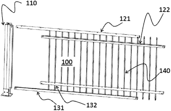
1. A modular railing comprising a plurality of modules (100) connected to each other, wherein each module (100) is an element of railing, comprising:
a. at least one supporting post (110) located at one end of said railing module (100), and suitable for being attached to the ground;
b. an upper horizontal bar (120) which connects said supporting post (110) to another supporting post (210) belonging to the adjacent module, and said upper horizontal bar (120) is coupled to said two supporting posts (110, 210) near their upper end;
c. a lower horizontal bar (130) which connects said supporting post (110) to said another supporting post (210) belonging to the adjacent module, and said lower horizontal bar (120) is coupled to said two supporting posts (110, 210) near their base;
d. a plurality of vertical rods (140) which connect said upper (120) and lower (130) horizontal bars;
and wherein said each module (100) is characterized in that:
each module (100) is identical to the modules (100) to which it is connected, regardless of the slope and the direction of installation;
said upper horizontal bar (120) comprises a couple of substantially constant section profiled elements, an upper profiled element (121) and a lower profiled element (122), wherein:
said upper profiled element (121) has a face facing upwards whose surface is substantially smooth,
said lower profiled element (122) has a face facing downward in which there are a plurality of holes;
said lower horizontal bar (130) comprises at least one upper profiled element (132) with a substantially constant section, which has a face facing upwards in which there are a plurality of holes;
said plurality of vertical rods (140) are coupled to said upper (120) and lower (130) horizontal bars, so that
the upper end of each of said vertical rods (140) is inserted into one of the plurality of holes present on said lower profiled element (122) of said upper horizontal bar (120), and said coupling has the prerogative not to form an interlocking joint and to allow said each vertical rod (140) to vary the angle it forms with said upper horizontal bar (120) so that said each vertical rod (140) maintains the verticality even if said upper horizontal bar (120) is not horizontally installed,
and wherein the lower end of each of said vertical rods (140) is inserted into one of the plurality of holes present on said upper profiled element (132) of said lower horizontal bar (130), and said coupling has the prerogative not to form an interlocking joint and to allow said each vertical rod (140) to vary the angle it forms with said lower horizontal bar (130) so that said each vertical rod (140) maintains the verticality even if said lower horizontal bar (130) is not horizontally installed;
wand wherein
said upper horizontal bar (120) and said lower horizontal bar (130) are connected at their ends to said two supporting posts (110, 210) by means of a constraint which allows to provide an adjustable angle with one degree of freedom;
said supporting post (110) comprises at least two longitudinal profiled elements:
an external longitudinal profiled element (111) arranged to be fixed vertically to the ground, and
an internal longitudinal profiled element (112) arranged to be coupled with said external longitudinal profiled element (111) so that said internal longitudinal profiled element (112) can rotate around its own longitudinal axis before being fixed in a definitive installation position, and once their coupling has been completed, said internal and external profiled elements (111, 112) are coupled side by side and parallel.
|