| CPC B29C 45/261 (2013.01) [A61M 5/347 (2013.01); B29C 45/16 (2013.01); B29C 45/1675 (2013.01); B29C 45/33 (2013.01); B29C 45/44 (2013.01); A61M 5/5086 (2013.01); A61M 2005/312 (2013.01); A61M 2005/3104 (2013.01); B29C 45/2618 (2013.01); B29C 45/36 (2013.01); B29C 2045/1601 (2013.01); B29K 2023/04 (2013.01); B29K 2023/10 (2013.01); B29K 2023/38 (2013.01); B29L 2031/56 (2013.01); B29L 2031/7544 (2013.01)] | 19 Claims |

|
1. Injection moulding process for producing a syringe (100) with an integrated closure element (101) comprising the following process steps:
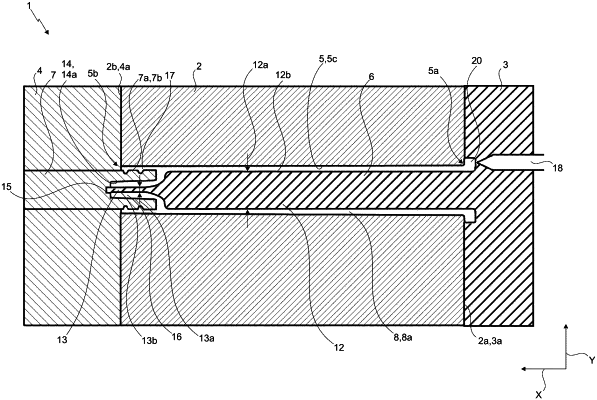
a) providing an injection moulding tool (1) which comprises a first (2), a second (3) and a third tool portion (4), wherein the first tool portion (2) has a mould cavity (5) open at both sides and extending along an axial direction (X), and wherein the second tool portion (3) has a first injection moulding core (6) and the third tool portion (4) has a second injection moulding core (7);
b) closing the injection moulding tool (1) such that the first tool portion (2) contacts the second (3) and third tool portion (4), and the first (6) and second injection moulding core (7) each enter the mould cavity (5) of the first tool portion (2) through an opening (5a, 5b) and finally contact each other, as a result of which these tool portions (2, 3, 4) form a first cavity (8);
c) injecting a first plastic material into the first cavity (8), as a result of which a hollow cylindrical syringe body (102) is formed with an end region (103) at its distal end (102a), wherein the end region (103) has an attachment element (105), provided with an inner thread (104), and a hollow cylindrical end piece (106) which is at least partially bordered by the attachment element (105);
d) cooling the tool portions (2, 3, 4), as a result of which the syringe body (102) cools and hardens;
e) bringing the first tool portion (2) into contact with a fourth tool portion provided with a mould cavity (9) closed at one end, as a result of which a second cavity (11) is formed at the distal end (102a) of the syringe body (102);
f) injecting a second plastic material into the second cavity (11), as a result of which the closure element (101) is integrally formed on the attachment element (105), wherein the first and the second plastic material do not enter into a cohesive connection;
wherein the first (6) and the second injection moulding core (7) extend along the axial direction (X), wherein the first injection moulding core (6) comprises a first cylindrical portion (12) with a first diameter (12a) and a second cylindrical portion (13) with a second, smaller diameter (13a), said first (12) and said second cylindrical portion (13) being adjacent in the axial direction (X), and wherein the second injection moulding core (7) has an additional mould cavity (14) open on one side in the axial direction (X) and a recess (15) on an inner wall (14a) bordering the additional mould cavity (14) in the axial direction (X);
wherein, with the contacting of the two injection moulding cores (6, 7) in process step b), the second cylindrical portion (13) of the first injection moulding core (6) is received in part in the recess (15) of the second injection moulding core (7);
wherein, between process steps d) and e), the second cylindrical portion (13) is displaced in the axial direction (X) away from the third tool portion (4), wherein, in the following process step f), the second plastic material enters the channel (108) of the end piece (106), as a result of which a sealing of the channel (108) is created,
wherein the first injection moulding core (6) is telescopically designed, wherein the second cylindrical portion (13) of the first injection moulding core (6) is displaced relative to the first portion (12) during process steps b) to d), wherein the second cylindrical portion (13) in process steps b) to d) is in a maximum axial position (21) such that the second cylindrical portion (13) contacts the second injection moulding core (7).
|