| CPC B25J 9/126 (2013.01) [B25J 9/042 (2013.01); H02K 16/02 (2013.01); B25J 9/044 (2013.01); H02K 2213/03 (2013.01)] | 10 Claims |

|
1. A planar articulated robot, comprising
a base,
a first inner rotor joint device provided on the base,
a first mechanical arm driven by the first inner rotor joint device, and
a manipulator connected to the first mechanical arm,
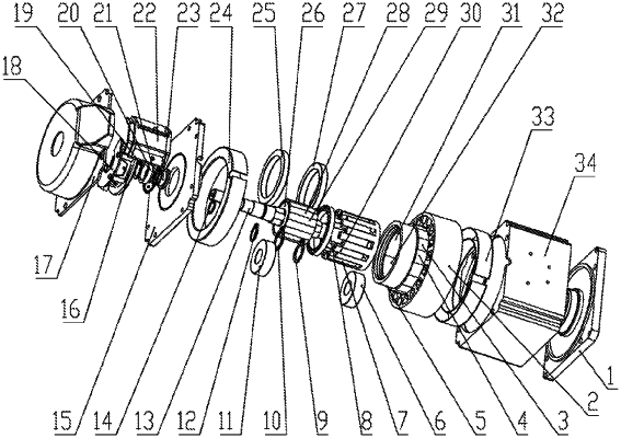
wherein the first inner rotor joint device comprises a rotating shaft fixedly connected to the first mechanical arm and extending along a longitudinal axis, a low-speed rotor assembly located on an outer periphery of the rotating shaft, a high-speed rotor assembly located on an outer periphery of the low-speed rotor assembly, a magnetizing ring located between the low-speed rotor assembly and the high-speed rotor assembly in a circumferential direction, a stator core located on an outer periphery of the high-speed rotor assembly with a certain gap therebetween in the circumferential direction, and a casing covering an outer periphery of the stator core and fixedly connected to the stator core, and a coil is wound around the stator core,
wherein the magnetizing ring comprises a magnetizing block skeleton and a plurality of magnetizing blocks uniformly arranged on the magnetizing block skeleton in the circumferential direction, the magnetizing block is made of a magnetically conductive material, and the magnetizing block skeleton is made of a non-magnetically conductive material,
wherein the low-speed rotor assembly comprises a low-speed rotor yoke stationary relative to the rotating shaft and low-speed rotor magnet N poles and low-speed rotor magnet S poles fixed on an outer periphery of the low-speed rotor yoke, the low-speed rotor magnet N poles and the low-speed rotor magnet S poles are alternately arranged in the circumferential direction, the high-speed rotor assembly comprises a high-speed rotor yoke and high-speed rotor magnet N poles and high-speed rotor magnet S poles fixed on an inner ring of the high-speed rotor yoke, motor magnet N poles and motor magnet S poles are provided on an outer ring of the high-speed rotor yoke, the high-speed rotor magnet N poles and the high-speed rotor magnet S poles are alternately arranged in the circumferential direction, and the motor magnet N poles and the motor magnet S poles are alternately arranged in the circumferential direction, and
wherein the high-speed rotor magnet N poles and the high-speed rotor magnet S poles are arranged as N1 pairs, the low-speed rotor magnet N poles and the low-speed rotor magnet S poles are arranged as N2 pairs, and the magnetizing blocks are arranged as N3 blocks, where N3=N1+N2.
|