| CPC B25B 23/1427 (2013.01) [B25B 13/465 (2013.01); B25B 23/141 (2013.01)] | 20 Claims |

|
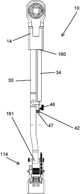
1. A torque wrench, comprising:
a handle extending along a longitudinal axis and configured to be grasped by a user;
a head configured to rotate a fastener about a rotational axis, the head comprising:
a first side;
a second side opposite the first side;
a ratchet mechanism including a through bore, the rotational axis extending through the through bore; and
a drive arbor that extends through the through bore, the drive arbor movable relative to the head along the rotational axis between a first and a second position;
a primary beam coupled to the handle and the head;
a secondary beam coupled to the head and selectively coupled to the primary beam;
a display comprising an indicator arrow and markings on a side of the handle;
a torque adjustment mechanism that moves the primary beam relative to the secondary beam, the torque adjustment mechanism comprising:
a rack gear; and
a gear coupled to the rack gear, wherein the indicator arrow moves when the gear rotates on the rack gear;
wherein, when the drive arbor is in the first position, the ratchet mechanism couples the drive arbor and the handle for rotation about the rotational axis in a first direction and allows the handle to rotate relative to the drive arbor in a second direction opposite the first direction; and
wherein, when the drive arbor is in the second position, the ratchet mechanism couples the drive arbor and the handle for rotation about the rotational axis in the second direction and allows the handle to rotate relative to the drive arbor in the first direction.
|