| CPC H02M 7/217 (2013.01) [H02M 1/10 (2013.01)] | 13 Claims |

|
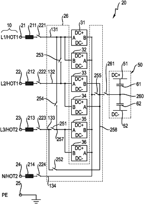
1. A rectifier arrangement (20) for rectifying an AC voltage (L1, L2, L3; HOT1, HOT2) into a DC voltage (DC+, DC−), the rectifier arrangement (20) comprising connections (21, 22, 23, 24), circuit arrangements (31, 32, 33, 34, 35, 36), an interconnection apparatus (26) and an intermediate circuit (50), wherein:
the connections (21, 22, 23, 24) comprise a first connection (21), a second connection (22), a third connection (23) and a fourth connection (24), the fourth connection (24) being connected to a neutral conductor of the AC voltage,
the intermediate circuit (50) has a first line (51), a second line (52) and at least one capacitor (61, 62) between the first line (51) and the second line (52),
the circuit arrangements (31, 32, 33, 34, 35, 36) each have: a first circuit arrangement connection (A) and a second circuit arrangement connection (B), each of the circuit arrangements (31, 32, 33, 34, 35, 36) further having a changeover arrangement (92) and a coil (91) connected in series with the changeover arrangement (92), the changeover arrangement (92) and the coil (91) of each of the circuit arrangements (31, 32, 33, 34, 35, 36) being between the first and second circuit arrangement connections (A, B) of the respective circuit arrangement (31, 32, 33, 34, 35, 36), an order of the changeover arrangement (92) and the coil (91) between the first circuit arrangement connection (A) and the associated second circuit arrangement connection (B) of the respective circuit arrangement (31, 32, 33, 34, 35, 36) being the same in each case,
the changeover arrangements (92) are interconnected to the first line (51) and to the second line (52) of the intermediate circuit (50), and
the interconnection apparatus (26) has switches disposed and configured to selectively enable at least a first configuration and a second configuration between the connections (21, 22, 23, 24) and the circuit arrangements (31, 32, 33, 34, 35, 36), wherein
in the first configuration, the circuit arrangements (31 to 36) form a first group (31, 32, 35, 36) and a second group (33, 34), with
the first connection (21) being electrically connected to the circuit arrangements (31, 32) in the first group (31, 32, 35, 36) but not electrically connected to the circuit arrangements (33, 34) in the second group (33, 34) and the fourth connection (24) being electrically connected to the circuit arrangements (31, 32, 35, 36) in the first group (31, 32, 35, 36), but not electrically connected to the circuit arrangements (33, 34) in the second group (33, 34), and with
the second connection (22) and the third connection (23) being electrically connected to the circuit arrangements (33, 34) in the second group (33, 34), but not electrically connected to the circuit arrangements (31, 32, 35, 36) in the first group (31, 32, 35, 36), whereby the first configuration enables two independent current paths via the first group and the second group of the circuit arrangements (31, 32, 33, 34, 35, 36), and wherein
in the second configuration at least one of the connections (24; 24, 21) is electrically connected to all of the circuit arrangements (31-36).
|