| CPC H02K 1/276 (2013.01) [H02K 1/17 (2013.01)] | 6 Claims |

|
1. A rotary electric machine comprising:
a stator comprising a stator core and an armature coil; and
a rotor comprising a shaft rotatable around a central axis, a rotor core coaxially fixed to the shaft and comprising a plurality of magnetic poles arranged along a circumferential direction, and a plurality of permanent magnets embedded in the rotor core and disposed in the plurality of magnetic poles respectively,
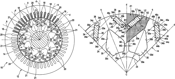
the rotor core comprising a plurality of polar central axes each passing the central axis and a center of the respective magnetic pole and extending radially with respect to the central axis, two embedding holes in each of the plurality of magnetic poles, provided on respective sides of the respective polar central axis, in which the respective permanent magnets are loaded, a plurality of cavity holes each provided between each respective adjacent pair of magnetic poles to oppose the embedding holes, respectively, with a gap therebetween, a first bridge portion defined between the two embedding holes on each polar central axis, and a second bridge portion defined between each respective adjacent pair of two cavity holes on each polar central axis,
in each of the plurality of magnetic poles, the two embedding holes and two permanent magnets each comprising an inner circumferential-side edge adjacent to the respective polar central axis and an outer circumferential-side edge adjacent to an outer circumferential surface of the rotor core, and disposed to be line symmetrical with respect to the respective polar central axis such that a distance from the polar central axis gradually expands from the inner circumferential-side edge toward the outer circumferential-side edge,
each of the embedding holes comprising a magnet loading region in which the respective permanent magnet is located, defined by an inner circumferential-side long edge and an outer circumferential-side long edge opposing parallel to each other, an inner circumferential-side cavity expanding from the inner circumferential-side edge of the respective permanent magnet towards the respective polar central axis, and an outer circumferential-side cavity expanding from the outer circumferential-side edge of the respective permanent magnet towards the circumferential surface,
each of the plurality of cavity holes being defined by a first edge and a second edge opposing with a gap from the inner circumferential-side long edges of the respective embedding holes provided in each respective adjacent pair of magnetic poles, and a third edge and a fourth edge opposing with a gap from the polar central axis of each of the adjacent pair of magnetic poles, and
where, in each magnetic pole, an axis electrically orthogonal to the respective polar central axis is defined as a q-axis,
A1 represents an area of a region defined by the respective polar central axis, the outer circumferential surface of the rotor core and a first imaginary linear line extending on the outer circumferential-side long edge of the respective embedding hole and intersecting the respective polar central axis and the outer circumferential surface of the rotor core,
A2 represents an area of a region defined by the respective polar central axis, the respective q-axis, the outer circumferential surface of the rotor core, a second imaginary linear line extending on the inner circumferential-side long edge of the respective embedding hole and intersecting the respective polar central axis and the outer circumferential surface of the rotor core, a third imaginary linear line extending on the first edge of the respective cavity hole and intersecting the respective polar central axis and the respective q-axis,
W1 represents a half-width of the first bridge portion, and
W2 represents a half-width of the second bridge portion,
the rotor core satisfying a relationship:
W2/W1≤(A1+A2)/A1.
|