| CPC H02K 1/22 (2013.01) [H02K 7/003 (2013.01)] | 4 Claims |

|
1. A rotor for a rotating electric machine comprising:
a shaft; and
a rotor iron core,
wherein
the shaft is coupled to the rotor iron core,
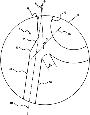
the rotor iron core includes: an outer edge portion housing a magnet; an inner edge portion coupled to the shaft; and a rib portion having a lightening portion that is formed inside between the outer edge portion and the inner edge portion,
the rib portion includes: a through-hole forming portion connected to the outer edge portion and having a through-hole inside; and a bridge portion connecting the through-hole forming portion and the inner edge portion,
the bridge portion includes: a second bridge portion protruding outward from a lower outer circumference of the through-hole forming portion; and a first bridge portion having one end connected to the inner edge portion and another end connected to the second bridge portion, and
a bent portion is provided at a position connecting the first bridge portion and the second bridge portion.
|