| CPC H02J 3/36 (2013.01) [H02H 1/0007 (2013.01); H02H 7/268 (2013.01); H02J 3/001 (2020.01); H02J 3/00125 (2020.01)] | 15 Claims |

|
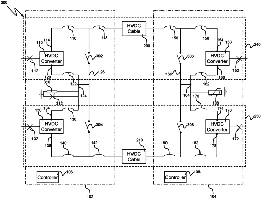
1. A high voltage direct current transmission system comprising:
a first station comprising first and second HVDC converters coupled in series via a first disconnector and a second disconnector;
a second station comprising series-connected third and fourth HVDC converters, wherein a neutral node coupling the third HVDC converter to the fourth HVDC converter is coupled to earth;
a first transmission line connecting a positive node of the first HVDC converter to a corresponding positive node of the third HVDC converter, wherein a first pole of the system comprises the first HVDC converter, the third HVDC converter and the first transmission line;
a second transmission line connecting a negative node of the second HVDC converter to a corresponding negative node of the fourth HVDC converter, wherein a second pole of the system comprises the second HVDC converter, the fourth HVDC converter and the second transmission line;
wherein a neutral node between the first disconnector and the second disconnector is coupled to a parallel combination of a resistance and a neutral bus ground switch for coupling the neutral node to earth.
|