| CPC H01S 5/0428 (2013.01) [G01S 17/931 (2020.01); H05B 45/327 (2020.01); H05B 45/3725 (2020.01); H05B 45/385 (2020.01)] | 11 Claims |

|
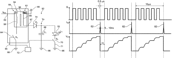
1. A control circuit for pulsed control of a light-emitting means, the control circuit comprising:
a switched-mode power supply unit with a first switch arranged in a primary circuit of the switched-mode power supply unit, wherein the switched-mode power supply unit has a primary-side connector for connection to a supply voltage, a secondary-side connector for supplying the light-emitting means and a switching input for operating the first switch;
a storage capacitor arranged between the secondary-side connector and a ground;
a second switch arranged in a current path in parallel with the storage capacitor, wherein the light-emitting means is positionable in the current path; and
a control unit to control the first and the second switch,
wherein the control unit is configured to operate the first switch in order to induce at least one charge pulse for charging the storage capacitor in a secondary circuit and to operate the second switch in order to discharge the storage capacitor while generating a light pulse via the light-emitting means, and
wherein the control unit is configured to coordinate operation of the first and second switches such that, at no time, the first switch and the second switch are simultaneously closed.
|