| CPC H01Q 3/36 (2013.01) [G01S 7/032 (2013.01); G01S 7/35 (2013.01); G01S 7/4008 (2013.01); G01S 7/4017 (2013.01); G01S 7/4026 (2013.01); G01S 7/4073 (2021.05); G01S 13/02 (2013.01); G01S 13/343 (2013.01); G01S 13/88 (2013.01); H03L 7/06 (2013.01); G01R 25/04 (2013.01); G01S 7/4069 (2021.05); G01S 13/931 (2013.01); G01S 2013/0254 (2013.01); H04B 1/10 (2013.01); H04B 1/109 (2013.01); H04B 1/1081 (2013.01); H04B 1/1638 (2013.01)] | 24 Claims |

|
1. A circuit, comprising:
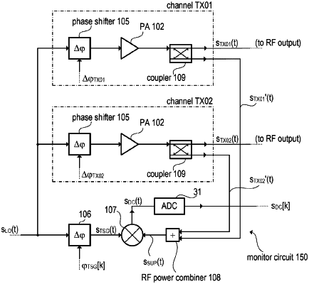
a radio frequency (RF) transmitter channel including an input node and an output node and being configured to receive an RF oscillator signal at the input node and to provide an RF output signal at the output node, wherein the output node is configured to be coupled to a transmit antenna;
a monitor circuit including a mixer configured to mix an RF reference signal and an RF test signal that represents the RF output signal to generate a mixer output signal, wherein the monitor circuit includes a coupler coupled to the RF transmitter channel and configured to couple out a portion of the RF output signal to generate the RF test signal;
an analog-to-digital converter configured to sample the mixer output signal at a plurality of sampling times in order to provide a sequence of sampled values; and
a control circuit coupled to the analog-to-digital converter and configured to:
provide a sequence of phase offsets by phase-shifting at least one of the RF test signal or the RF reference signal using one or more phase shifters such that a phase offset between the RF test signal and the RF reference signal is successively increased according to the sequence of phase offsets,
wherein the analog-to-digital converter is configured to sample the mixer output signal for each phase offset of the sequence of phase offsets to provide the sequence of sampled values,
calculate a spectral value of the sequence of sampled values, and
calculate estimated phase information indicating a phase of the RF output signal based on the spectral value.
|