| CPC H01M 10/0481 (2013.01) [H01M 50/209 (2021.01); H01M 50/242 (2021.01); H01M 50/264 (2021.01); H01M 50/271 (2021.01); H01M 50/289 (2021.01); H01M 50/291 (2021.01); H01M 2220/20 (2013.01)] | 9 Claims |

|
1. A spring plate configured to be assembled with an array of cells within a battery pack housing, the spring plate comprising
a first surface that is configured to face an outermost cell of the array of cells,
an opposed second surface that is configured to face an inner surface of the battery pack housing, and
a peripheral edge that joins the first surface to the second surface, the peripheral edge including a first edge, a second edge, a third edge and a fourth edge, the first, second, third and fourth edges each corresponding to a unique side of the spring plate, the second edge being parallel to, and spaced apart from, the first edge, and the third edge being parallel to, and spaced apart from, the fourth edge,
wherein
a distance between the first edge and the second edge corresponds to height dimension of the spring plate,
a distance between the third edge and the fourth edge corresponds to a width dimension of the spring plate,
the width dimension of the spring plate is equal to or greater than the height dimension of the spring plate,
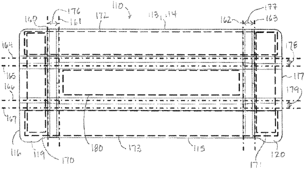
the first surface is bent in a first direction about a first bend line that is perpendicular to the first edge,
the first surface is bent in a second direction about a second bend line, the second bend line being perpendicular to the first edge and spaced apart from the first bend line, the second direction being opposed to the first direction,
the first surface is bent in the second direction about a third bend line, the third bend line being perpendicular to the first edge and spaced apart from the first and second bend lines,
the first surface is bent in the first direction about a fourth bend line, the fourth bend line being perpendicular to the first edge and spaced apart from the first, second and third bend lines,
a first peripheral region extends between the third edge and the first bend line,
a first transition region extends between the first bend line and the second bend line,
a central region extends between the second bend line and the third bend line,
a second transition region extends between the third bend line and the fourth bend line,
a second peripheral region extends between the fourth bend line and the fourth edge,
the first peripheral region is coplanar with the second peripheral region,
the central region is parallel to the first peripheral region and offset relative to the first peripheral region,
a width of the first peripheral region is at least three times a width of the first transition region,
a width of the second peripheral region is at least three times a width of the second transition region, and
a width of the central region is at least three times the width of the first peripheral region and at least three times the width of the second peripheral region.
|