| CPC G02F 1/136204 (2013.01) [G02F 1/13452 (2013.01); G02F 2202/22 (2013.01)] | 19 Claims |
|
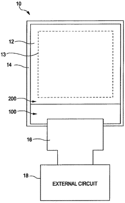
1. A liquid crystal display device comprising:
a first substrate including pixel electrodes and a common electrode in a pixel area and including a peripheral circuit and a dummy wiring in a peripheral area surrounding the pixel area;
a second substrate including a translucent conductive film provided at an opposite side of the second substrate to the first substrate side, the translucent conductive film overlapping the pixel area, the peripheral area, and the dummy wiring in plan view; and
a liquid crystal layer between the first substrate and the second substrate, wherein
the peripheral circuit includes a common wiring supplying a common electric potential to the common electrode, the common wiring being separated from the dummy wiring,
the dummy wiring is located between the peripheral circuit and an outermost edge of the first substrate at the outermost edge of the first substrate,
the dummy wiring is made of a continuous metal layer surrounding the pixel area and peripheral circuit on at least three sides of the first substrate and is connected to a ground potential outside the first substrate to ground the static electricity, and
the dummy wiring is provided to discharge electric potential rise on the first substrate that occurs due to coupling with electric potential rise of the translucent conductive film on the second substrate.
|