| CPC G02B 27/0031 (2013.01) [G02B 26/085 (2013.01); G02B 26/0833 (2013.01); G02B 26/10 (2013.01); G02B 26/101 (2013.01); G02B 27/0006 (2013.01)] | 13 Claims |

|
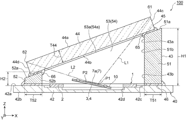
1. A mirror unit comprising:
a base including a main surface and a rear surface,
an optical scanning device including a movable portion swingable around a predetermined axis and a mirror surface provided on the movable portion, the optical scanning device being disposed on a side of the main surface with respect to the base,
a frame member disposed on the side of the main surface with respect to the base so as to surround the mirror surface when viewed from a first direction; and
a window member attached to the frame member so as to cover an opening of the frame member,
wherein the window member is inclined with respect to the mirror surface,
wherein the main surface is provided with a first depression,
wherein a bottom surface of the first depression is provided with a second depression,
wherein the optical scanning device is disposed on the bottom surface of the first depression, and
wherein at least part of the movable portion of the optical scanning device faces a bottom surface of the second depression.
|