| CPC F22B 37/58 (2013.01) [F22B 37/007 (2013.01)] | 5 Claims |

|
1. A method of disassembling a steam generator including:
a body portion having a cylindrical shape and extending in an axial direction,
a water chamber provided below the body portion,
a tube plate provided to partition between the body portion and the water chamber, and arranged along a plane orthogonal to the axial direction, and
a plurality of heat transfer tubes inserted into a plurality of through-holes formed to penetrate the tube plate in the axial direction, wherein
the steam generator is formed with a primary region below the tube plate and a secondary region above the tube plate,
the method comprising:
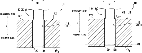
a step of obtaining a disassembly target including the tube plate and a part of the heat transfer tubes by cutting end surfaces of the heat transfer tubes and the tube plate on the primary region side across the tube plate and cutting the heat transfer tubes to protrude from the tube plate on the secondary region side;
a step of specifying the heat transfer tube fixed to the tube plate, among the heat transfer tubes included in the disassembly target;
a step of releasing fixation between the part of the heat transfer tube and the tube plate by inserting a TIG heating head into the part of the heat transfer tube fixed to the tube plate to heat the heat transfer tube; and
a step of pulling out the part of the heat transfer tube from the through-hole, wherein
in the step of releasing the fixation, the TIG heating head is inserted from the primary region side, and
in the step of releasing the fixation, the TIG heating head is moved to a plurality of streaks only in a direction from the primary region side to the secondary region side along a longitudinal direction inside the part of the heat transfer tube.
|