| CPC F04D 29/284 (2013.01) [F04D 17/10 (2013.01); F04D 29/30 (2013.01); F01D 5/048 (2013.01); F01D 5/141 (2013.01)] | 7 Claims |

|
1. An impeller of a centrifugal compressor, comprising:
a hub;
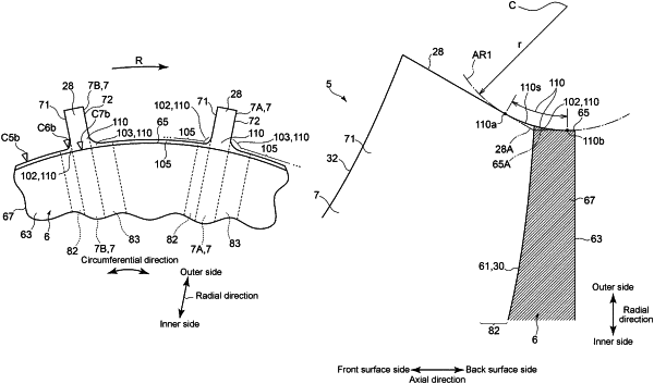
at least one airfoil portion erected on a hub surface of the hub, the at least one airfoil portion having a trailing edge configured such that a distance between the trailing edge and an axis of the centrifugal compressor increases with increasing distance from a back surface of the hub; and
a first fillet which is formed on a radially outer side of an outer peripheral surface of a back plate portion forming a back surface portion of the hub, the first fillet connecting the outer peripheral surface and the trailing edge of the at least one airfoil portion,
wherein the first fillet has a curved portion having a center of curvature exists on a radially outer side of the outer peripheral surface, in a meridional cross-section of the impeller, and
wherein an end edge of the curved portion on a side of the outer peripheral surface is located at the back plate portion.
|